Denso Training. Denso Training - Agenda. Hardware Overview Jogging the robot Teaching Positions (using the Teach Pendant) Configuring the Robot Programming (Using the Teach Pendant) I/O Interfacing (Hardware) Overview of Development Software Maintenance.
Une image / un lien ci-dessous est fourni (tel quel) pour télécharger la présentation
Politique de téléchargement : le contenu du site vous est fourni TEL QUEL pour votre information et votre usage personnel ; il ne peut être vendu, concédé sous licence ni partagé sur d’autres sites sans l’accord de son auteur.Le contenu vous est fourni TEL QUEL, pour votre information et votre usage personnel uniquement.Téléchargez la présentation en cliquant sur ce lien.Lors du téléchargement, si vous ne parvenez pas à télécharger une présentation, l’éditeur a peut-être supprimé le fichier de son serveur.Pendant le téléchargement, si vous ne parvenez pas à obtenir une présentation, le fichier a peut-être été supprimé par l’éditeur.
Denso – Modes of Operation • The Robot has 3 modes of operation. • Manual- operate the robot from the teach pendant. • Teach Check – restricted automatic operation • Auto – Allows the robot to operate automatically. (Pendant Control) (PLC control) Manual and Teach Check mode speed is limited to 10% of the robot max speed.
Denso – Manual Operation – X-Y Mode -VS • XY Mode- allows moving the robot arm in base coordinates (The origin is located at the center of the base.) (WORK 0)
Robot Exercise - Jogging • Enable Auto Switch to Manual • Pendant Mode Key Switch to Manual Mode • Clear E-Stops • Manual Mode • ARM (Speed 10%) • P(Position) -J(Joint) -T(Transform) buttons -Viewing Current Position using XY coordinates, Joint coordinates or tool coordinates • OpeMode – Selects coordinate System for movement • Motor ON • Joint/Coordinate Movement using J1 through J6 • Move Robot using all three operating modes • Inching the Robot
Denso – Work Coordinates • Up to 7 more work coordinate systems may be specified, WORK 1 – WORK7.
Denso –Tool Coordinates • Multiple Tool coordinate systems may also be defined, TOOL 1 – TOOL 63. • TOOL 0 is always defined as at the flange of the robot. (TOOL 0)
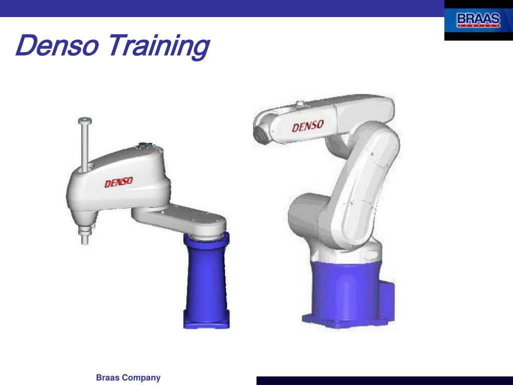
Denso – Figures of the Robot -Scara • The two figures for the SCARA robot. Both show the robot at the same location with a lefty and righty figure.
Denso – 6 Axis Robot -Shoulder Figure (1) Shoulder figure The rotary axis of the 1st axis is defined as the boundary between LEFTY and RIGHTY. When viewed from the normal line on the side of the arm link, if point Pw exists in the left-hand side of the rotary axis of the 1st axis, the figure is LEFTY; if point Pw exists in the right-hand side, it is RIGHTY.
Denso – 6 Axis Robot –Elbow Figure The centerline of the arm link (connecting the shoulder with elbow) is defined as the boundary between ABOVE and BELOW. If point Pw exists in the + side of the centerline, the figure is ABOVE; if point Pw exists in the -side, it is BELOW.
Denso – 6 Axis Robot-Wrist Figure The rotary axis of the 4th axis is defined as the boundary between FLIP and NONFLIP. If the normal line on the flange surface tilts up the rotary axis of the 4th axis, the figure is FLIP; if it tilts down the rotary axis, it is NONFLIP.
Denso – 6 Axis Robot-6th Axis Figure If the rotation angle of the 6th axis is within the range of -180 to 180° around the Z axis in mechanical interface coordinates, the figure is SINGLE; if it is within the range of 180° to 360° or -360° to -180°, the figure is DOUBLE.
Denso – Preparation for Programming • To program we need to understand: • Variables • Interpolation Control • Confirming Reach Position • Basic Programming Commands • TAKEARM, MOVE, APPROACH, DEPART, SET, RESET, DELAY, WAIT
Denso – Variables (Global) Access: [F1 Program] – [F4 Variable] –[F12 VarsUsed] *All vars configured to 200 on demos. *Please only use variables numbered greater than 100 for the class
Denso –Interpolation Control -Point to Point • PTP (Point to Point) can be defined as the movement from one point to another point. The path on which the robot moves depends on the robot posture and is not always a straight line. • If you designate a Type P or Type T variable as the PTP motion destination position and the designate robot figure, the robot moves so that the robot becomes the designated robot figure. If you do not designate any robot figure it will be the current robot figure.
Denso –Interpolation Control -Continuous Path - Linear • Continuous Path (CP) control manages interpolation so that the path to reach the motion destination position will be a straight line. • If you designate “L” for designation of the interpolation method with the motion control command, the robot executes the CP motion. • When CP control is executed, the robot cannot simply move to the position of a different figure. If you designate a different figure a error may occur. • If the first motion of a program is CP control, the motion may not be available depending on the robot position. PTP control is recommended for the first motion command in the program.
Denso –Interpolation Control - Continuous Path – Circular (ARC) • ARC interpolation control manages interpolation so that the path to reach the motion destination position will be an arc. • If you designate “C” for designation of the interpolation method with the motion control command, the robot executes the ARC motion. • When CP control is executed, the robot cannot simply move to the position of a different figure. If you designate a different figure an error may occur. • If the first motion of a program is ARC control, the motion may not be available depending on the robot position. PTP control is recommended for the first motion command in the program.
P100 P101 Denso – Programming Exercise -Manual • Move between the two Points • Select the position you want to move to • Make sure motor Power is on • From this screen select [F4 Move] • Select PTP or CP movement • Hold OK button to move
Denso – Programming Exercise • Remove comment mark from TAKEARM • 0001 ‘!TITLE “PRO4” • 0002 PROGRAM PRO4 • 0003 TakeArm • 0004 • 0005 END
Denso - Programming • TAKEARM (Statement) • Function • Gets an arm group. Upon the execution of this statement, the programmed speed, acceleration and deceleration will be set to 100. If the gotten arm group includes any robot joint, this statement restores the tool coordinates and work coordinates to the origin. • Format • TAKEARM[<ArmGroupNumber>][<KEEP=DefaultValue>] • Note: • TAKEARM command must be issued before any command that may effect robot arm, Ex: SPEED
Denso – Programming Exercise • Press [F1 New Line] and type APPROACH • 0001 ‘!TITLE “PRO4” • 0002 PROGRAM PRO4 • 0003 TakeArm • 0004 • 0005 APPROACH P, P1, @0 F1, S=100 • 0006 • 0007 END
Denso - Programming • APPROACH (Statement) • Function • The robot moves to a position away from the <Base position> by <Approach length> in the Z direction of the tool coordinate system. • Format • APPROACH <Interpolation method>, <Base position>,[<Path start displacement>]<Approach length>[,Motion option>][,NEXT] • Example: • APPROACH P ,P1,@0 F1,S=100
Denso –Confirming Reach Position • Pass Motion, @P • is to pass the vicinity of a taught motion position or relative position • End Motion, @## • is determined if the robot has reached the destination position when the command value of the servo system meets the destination position. • Encoder Value Check Motion, @E • is determined when the encoder feedback value is within a designated window around the destination position.