The CBM Experiment
210 likes | 369 Vues
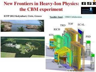
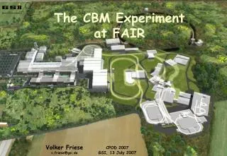
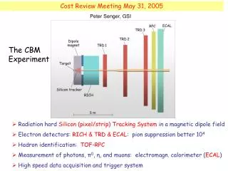
Cost Review Meeting May 31, 2005. Peter Senger, GSI. The CBM Experiment. Radiation hard Silicon (pixel/strip) Tracking System in a magnetic dipole field Electron detectors: RICH & TRD & ECAL : pion suppression better 10 4 Hadron identification: TOF-RPC

The CBM Experiment
E N D
Presentation Transcript
Cost Review Meeting May 31, 2005 Peter Senger, GSI The CBM Experiment Radiation hard Silicon (pixel/strip) Tracking Systemin a magnetic dipole field Electron detectors: RICH & TRD & ECAL: pion suppression better 104 Hadron identification: TOF-RPC Measurement of photons, π0, η, and muons: electromagn. calorimeter (ECAL) High speed data acquisition and trigger system
Total cost CBM Technical Status Report January 2005
Silicon Tracking System 3 Pixel Stations and 4 Strip Stations (acceptance 2.5o < θ < 25o): STS 1 - 3 Silicon Pixel Vertex Detector • Design goals: • low materal budget: d < 200 μm • single hit resolution < 20 μm • radiation hard (dose 1015 neq/cm2) • read-out time 25 ns • R&D on Monolithic Active Pixel Sensors (MAPS): • pitch 30 μm • thickness below 100 μm • single hit resolution : 4 μm • radiation tolerant (1013 neq/cm2) • ultimate read-out time few μs
Design studies on a MAPS detector station Vertex Detector section of the CBM Silicon Tracker Existing MAPS detector “MIMOSA 5” (1.7 x 1.9 cm2) CBM MAPS chips will look differently: Chip size: ~0.5 x 1 cm2, 50% sensor 50% r/o. CBM MAPS ladders will consist of 5 chips. active readout MAPS detector module: ladders mounted on either side of a substrate providing (active?) cooling Two inner and two outer sectors, routing of readout microcables.
Silicon Strip Tracker 4 Strip tracking stations Tracking Stations Nr. 4 and 6 Double sided Si-Strip detectors: thickness 100 - 150 μm pitch 25 μm Stereo angle 15o
Design of a fast RICH • Design goals: • electron ID for γ> 42 • e/π discrimination > 100 • hadron blind up to about 6 GeV/c • low mass mirrors (Be-glass) • fast UV detector
RICH components Radiator Vessel volume ~ 60 m3 Photon-detector: 105 PM tubes, 6 mm ø Mirror: 19 m2, Be-glass (X = 1.25% X0)
RICH the cost of the items include material, design, construction
Design of a fast TRD • Design goals: • e/π discrimination of > 100 (p > 1 GeV/c) • High rate capability up to 100 kHz/cm2 • Position resolution of about 200 μm • Large area ( 450 - 650 m2, 9 – 12 layers) Simulation of pion suppression: MWPC based TRD . 90%
TRD (MWPC based) the cost of the items include material, design, construction
Development of a large-area high-rate timing RPC • Design goals: • Time resolution ≤ 80 ps • Rate capability up to 20 kHz/cm2 • Efficiency > 95 % • Large area 100 m2 • Long term stability Layout options shielded RPC prototype single cell RPC
TOF-RPC The cost include material, engineering design, and construction
The Electromagnetic Calorimeter LHCb CBM -ECAL ECAL region Inner Middle Outer Cell size 4x4 cm2 6x6 cm2 12x12 cm2 No. of channels 6300 6400 4100
ECAL The cost include material, engineering design, and construction
Superconducting Dipole Magnet "Alligator" Parameter Quantity Dimension Weight of yoke 37 ton Coil windings 270 Gap maximal 845 mm Gap minimal 368 mm Ampere turns 600000 Field length 1200 mm Maximum field 1.7 T Time to cool down 48 hours Time to ramp-up field 45 minutes Thermal stream to Helium vessel 6 W Thermal stream to Nitrogen screen 30 W
Superconducting dipole magnet Totel sum 2245
L1 Select L2 Select Self-triggered FEE – Data Push DAQ Detector Self-triggered front-end Autonomous hit detection fclock FEE No dedicated trigger connectivity All detectors can contribute to L1 Cave Shack DAQ Large buffer depth available System is throughput-limited and not latency-limited High bandwidth Modular design: Few multi-purpose rather many special-purpose modules Special hardware Archive archive rate few GByte/s
DAQ the costs of the items include material, design, construction A reliable bottom-up components based cost estimate can only beprovided after the major architectural and technology choices are done. Currently the best approach is to scale a similar experiment..BTeV used to be the most similar, with a L1 displaced vertex trigger.The BTeV TDR, which was reviewed and approved, states FEE data rate: 500 GB/sec L1/2/3 trigger uses ~1000 FPGA and 1000 software processors ready-date: October 2009 for 50% capacity, August 2010 for 100% investment cost: 10 M€ (or 12 M$) for DAQ + trigger (without contingency) CBM has a factor 2 higher FEE data rate (~ 1 TB/sec) CBM has 5 years more time about a factor 5 gain from Moore's law CBM DAQ and event selection: 5 M€
Infrastructure the cost of the items include material, design, construction
Total cost CBM Comparison: Tech. Status Report Jan 2005 Cost Review May 2005