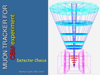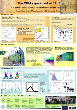
MUON TRACKER FOR CBM experiment
MUON TRACKER FOR CBM experiment. Detector Choice. S. Chattopadhyay, VEC Centre. INDIA-CBM COLLABORATION. Collaborators: VECC SINP IOP PU RU AMU CU BHU IIT-KGP Expressed interest BARC JU. Simulate, design, build and operate a large part of CBM muon system.

MUON TRACKER FOR CBM experiment
E N D
Presentation Transcript
MUON TRACKER FOR CBM experiment Detector Choice S. Chattopadhyay, VEC Centre
INDIA-CBM COLLABORATION Collaborators: VECC SINP IOP PU RU AMU CU BHU IIT-KGP Expressed interest BARC JU Simulate, design, build and operate a large part of CBM muon system • Two (Indian) collaborations meetings so far • Discussed details of physics/HW/simulation • Simulation started big way • (Two persons visited GSI for 3 months) • Proposal submitted to funding agency for • building significant part of CBM • muon system
OUR EXPERIENCE IN HEAVY ION EXPERIMENTS WA93/WA98 STAR ALICE RPC for Neutrino Observatory
ALICE PMD Layout (Data taking position) Converter + Support Plate Super Module 8 Supermodules in 2 planes Total channels Preshower+Veto = 221,184 Unit Module 48 Nos. Total Cooling by air circulation Unit module components Honeycomb (4608 cells) Top, bottom PCBs
What we have achieved so far in STAR PMD • PMD in STAR : NIM A 499, 751 (2003) • First physics data taken : 2004. • First physics paper in Physical Review Letters August 2005 Detector laboratory Electronics laboratory
ALICE MUON tracking station2 Two tracking chambers Four quadrants in each chamber Distance from the vertex : 6860 mm Acceptance : 20 - 100 Station 2 Active area : I) Inner radius : 231 mm ii) Outer radius : 1190 mm Thickness of the chamber : 75 mm (including readout electronics) Thickness of the station : 300 mm Beam
Highest hit density expected at various muon stations (URQMD, central) Effective rate ~10MHz/Cm2
Muon Chambers: Design parameters and method.... • Should be able to handle highest rate • Should have good position resolution • Should be possible to make in large area • FEE connections and taking them out is a concern.. • COST
Comparison of detectors.. Both GEM & MICROMEGAS are suitable for high rate applications
GasElectronMultiplier - GEM Manufactured with technology developed at CERN 100-150 µm Typical geometry: 5 µm Cu on 50 µm Kapton 70 µm holes at 140 mm pitch
GEM.. Thin metal-coated polyimide foil chemically etched to form high density of holes. On application of a voltage gradient, electrons released on the top side drift into the hole, multiply in avalanche and transfer to the other side. Proportional gains above 103 are obtained in most common gases. F. Sauli, Nucl. Instrum. Methods A386(1997)531
Single-Double-Triple GEM Multiple structures provide equal gain at lower voltage The discharge probability on exposure to a particles is strongly reduced For a gain of 8000 (required for full efficiency on minimum ionizing tracks) in the TGEM the discharge probability is not measurable. S. Bachmann et al, Nucl. Instr. and Meth. A479 (2002) 294
Mesh Choice for MICROMEGAS.. Copper with integrated polyimide pillars (by etching technology Electroformed mesh SS woven mesh Advantages of Woven mesh 1. they exist in rolls of 4 m x 40 m and are quite inexpensive, 2. they are commonly produced by several companies over the world, 3. there are many metals available: Fe, Cu, Ti, Ni, Au, 4. they are more robust for stretching and handling.
Double mesh MICROMEGAS • Protection of Front end electronics from discharges • Cathode and readout pad plane are separated S. Kane et al./NIM A 505(2003)215-218 Purdue University
GEM… • High (100 mm) pitch • Direct electron signal no losses • Efficient ion collection • Easy to build • Robust to aging • Multi-stage structureslarge gains (103-104) • Low mass construction no wire frames
Issues of implementing GEM in Large area detectors.. • Only a few sources of supply • Large area GEM foils are difficult to fabricate. Small foils leave large dead areas in the tracking plane • Single stage GEM gain is low • Expensive (relative)
MICROMEGAS.. High (50 mm) pitch Direct electron signal no losses Funnel effect very efficient ion collection Easy to build dead zones potentially small Robust to aging Good electro-mechanical stability large gains (103 -104) Low mass construction no wire frames
MICROMEGAS : Some practical questions • Choice of wire mesh : Woven vs. electro-formed vs. etched copper clad kapton • Bulk MICROMEGAS – pillars of photo resist. Also other spacers like fish line • How to optimize ion backflow? Practical limitations of mesh aperture(LPI) • Minimizing discharges due to heavily ionizing particles ( nuclear recoils) • Choice of gas mixtures • Muon tracking at high rates: how to widen pad response function? • Need of resistive coating ( Cermet, graphite) • Other readout schemes : Second anode mesh and a separate readout pad plane • Practical construction : • How to paste mesh to frame? how to protect mesh edges? • How much Minimum frame width? • How to tap HV connection? • Frame material, rigidity • Mesh sag due to temperature fluctuations • Invar mesh (shadow mask of CRTs)? • Effect of pad ridges on field uniformity
Thick GEM.. Worth investigating further for CBM Muon Tracker..
Design concepts.. • Wheel type design of planes with 8 sector type chambers in each plane • Each sector with a single woven mesh supported on insulating pillars or THGEM • Readout pad granularity to vary from 3mm to 7mm pads radially in 3 zones - to keep occupancy within 10% level • (needs further optimization study)
SUMMARY: • Detector technology exists (in-principle) to deal with • CBM muon environment. • GEM/Micromegas/Silicon are possible options • Detailed R&D needed … • Combination of various technological options to be • put together • EU project is just right • Early decision on di-lepton option will be helpful
Our Preparation so far.. Working on simulation in big way .. Have started building GEM-based prototype which we plan to test sometime soon.. Would like to read out with CBM specific (close to) chip. Have started the procurement of mesh for micromegas