Download
1 / 47
470 likes | 635 Vues
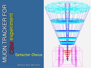
Chamber R&D for CBM Muon Tracker Anand Kumar Dubey VECC, Kolkata. Muon detector requirements:. Main issues: The first plane(s) has a high density of tracks -- detector should be able to cope up with high rate. ~ 10 MHz/cm 2

E N D
Chamber R&D for CBM Muon Tracker Anand Kumar Dubey VECC, Kolkata
Muon detector requirements: Main issues: • The first plane(s) has a high density of tracks -- detector should be able to cope up with high rate. ~ 10 MHz/cm2 • good position resolution • Should be radiation resistant • Large area detector – modular arrangement • Should be cost effective • Use of detectors based on micropattern technology --- GEMs, THGEMs and Micromegas
140m 70m Gas Electron Multiplier (GEM) and its working principle --- a 50 micron polyimide foil with a 5 micron Cu layer deposited on both sides of polyimide • Active medium is a gas mixture. • electron multiplication takes place in holes of two copper foils separated by kapton • Amplification may use 2 or 3 stages. • Maximum size ~30 x ~30 cm2 • Cost ~$ 700 (made at CERN)
Multi GEM configurations.. We have assembled and tested both --- double and triple GEM.
Double GEM stack under test (at VECC) Gas Inlet Gas mixture: Ar/CO2 – 70/ Readout : single pad 1cm x 1cm
3GEM: Test with Fe-55 (at VECC) readymade stretched and framed GEM foils from CERN Gas mixture: Ar/CO2-70/30 Readout pad: 8mm x 3.5 mm Only one pad connected
3GEM: Test with Fe-55 3GEM: Gain vs. Vgem
Testing of GEM chambers @GSI First beam test September 28-30, 2008, SIS 18 6 hours of beamtime we had carried two chambers –2GEM and 3GEM chambers Testing with proposed FEE for CBM -- first successful test with n-XYTER readout chip(64 channels connected) Testing of the chambers with real DAQ Response to 3.5 GeV protons. --- Obtained MIP spectra, saw the beam spot --- cluster spread….granularity test could not be done as only alternate channels were bonded. Second beam test Aug 29-September 8th , 2009, SIS 18 --- Carried two triple GEM chambers the difference being that one of the chambers had a larger induction gap than the other.
GEMS 1 2 3 Drift plane (inner side copper plated) 12 x cm 12 cm x 10 mm Schematic of Chamber assembly for beam test at GSI 5 CERN made GEM foils obtained from Area: 10cm x 10cm One triple GEM One double GEM Assembled at VECC Readout PCB Double GEM chamber: Drift gap: 7mm Inductive gap: 1.5mm Transfer gap: 1mm Triple GEM chamber: Drift gap: 6.5 mm Inductive gap = 1.5mm Transfer gap = 1mm
Detector fabrication at VECC for Sep08 beam test Outer side of the readout PCB Readout: 256 Pads with staggered layout each pad 8 mm x 3.5 mm 10 ohm Resistors for protection
3 days beam time (2hrs/day) 1st Day: • Triple GEM • Beam seen, MIP peak visible > 2700V 2nd day: Triple GEM • Voltage and DAQ threshold scan • Tried to optimise voltages 3rd day: Double GEM • 3 voltages, same threshold • one run with high intensity beam • 3 small runs with new connector
Sr-90 tests with nXYTER+3GEM HV 3050V HV 3150V HV 2950V
Test beam- 2008 Beam Region fired BEAM SPOT 3-GEM Only alternate channels hit High intensity run 2-GEM
The readout PCB only alternate channels connected to nXYTER. beam
Triple GEM: Variation of MIP MPV and no of cells 3100V (Vgem~350) MPV increases slowly with HV (note: only alternate channels fired) 2800V(Vgem~320) V_gem=320 No of cells : mostly 1-1.5
Relative detected fraction Fraction =1 at 3100V Do we see plateau at 3000V? Saturated fraction Increases with HV up to ~22%. (the dynamic range of n-xyter is 20 fC) Triple GEM Saturation fraction
Observations from test beam08 experience: Both triple and double GEM gives MIP peak and Sr90 spectra Triple GEM: • MIP peak and detection eff increases with HV • Eff plateau at 3000V? • Number of cells/cluster increases slowly • Gain ~ 10^3 • Saturation goes up with HV but slowly Double GEM: • MIP peak seen >2900V(delta_V ~ 347 V) • No of cells ~ 1.5 • detection eff, MIP peak position, cluster-size does not change drastically for higher beam intensity -- not everything fine with the AUX signal. so could not perform the efficiency studies. -- Moreover, with alternate channels connected, cluster size and efficiency studies not possible with nXYTER. .
Questions remaining from last test beam • Absolute efficiency and HV dependence • Beam intensity dependence • Absolute gain estimate • Uniformity over small zone New questions: Pad multiplicity/cluster size Position resolution Required dynamic range before saturation Induction gap (does it increase cluster size?)
Readout Board for Test beam Aug-Sep 09 Inside view Outside view Two triple GEM chambers were fabricated : det 01 – with two different pad sizes(shown above) det02 -- same size pads but with larger induction gap
Test with Fe-55 before shipping to GSI det01 Tests done using standard NIM electronics at VECC
Test beam Aug-Sep: 2009 • Main Features: • --- more number of days as compared to last test beam • --- A new fully connected nXYTER board • --- An X--Y movement facility was provided exclusively for the GEM ch. • --- A better trigger arrangement for efficiency studies. • --- STS, RICH + Panda (parasitic run with Panda) • Summary of data taken: • 2 ROCs connected to one half of each detector • small cell size in det1 and large cell size in det 2 • one day data: Both large pad sizes • --- First Day – Problem with SY1527 calibration • --- Movement in both X and Y • (Beam spot moved and went away) • Aux signals: • 2 days data where Aux from different detectors can • be correlated (can be used for position resolution) • One day data for good AUX (crucial for eff) • Trigger data: • One run for 10 minutes
Fe-55 spectra with full readout Test with Fe55 + nXYTER using 3GEM Readout for Pad#20 ADC ADC DeltaV (GEM) ADC
actual pad readout plane Protons of 2.3 Gev/c the beam profile on Respective planes
nXYTER Baseline(position of zero signal) study using triggered mode data (no source/beam) HV nXYTER (I uA) mean ADC rms HV nXYTER (I uA) mean ADC rms 459 2109.61 6.82203462 2094.02 5.62808466 2105.38 7.27812470 2104.08 5.26833474 2128.5 4.3662478 2137.73 4.57708482 2139.69 5.05639497 2143.44 4.50543513 2145.04 4.44678 459 2217.08 6.69564462 2201.52 5.48452466 2213.07 7.14234470 2211.54 5.27438474 2235.52 4.32994478 2245.7 4.54713482 2247.27 5.02932497 2250.96 4.41502513_vth50 32 2252.64 4.32795 Pad # 32 Pad # 20 -- one can look at all 128 pads -- GEM bias voltage doesn’t affect the baseline the change maybe about 1-2 % This nothing as compared to the drift due to temperature ! Any plan of controlling this in future revisions ?
Time difference between aux and GEM ROC Procedure: Select fired GEM cells in 900-1200 nsec after last Aux. All Aux channels: eff:10% Aux-Channel=2 (4 fold) eff = 71% Offset + Drift time(~160 ns) -- why this large spread ?? ---- copied from Sauli’s slides
BEAM SPOT ON TWO CHAMBERS Cell size: 1.6mm x 16mm Cell size: 3.5mm x 8mm
Correlation between GEM1 and GEM2 Position of spots (cell units) from 2 detectors Shown (well-correlated) MIP distribution of hit cell
ADC distribution of main cell and variation with HV 4 fold increase in ADC for a deltaV(GEM) increase by 50V
PAD multiplicity (Same granularity but different induction gap) • Two back to back • detectors similar pad • multiplicity.. • No effect of increased • induction gap? • (Last day’s data, det2 • had low eff, went • bad after 3500V) Depends on beam profile, needs correlating with beam tracker -- no effect of induction gap on the cluster size
Efficiency of detector 1 (large pad size) Only aux2 taken, all aux gives low eff (23%). Time window: 900-1200 nsec Detector2 (5thsept data) goes upto 71% • Maybe we need 5-fold coincidence • Above>3600V, nXYTER saturates, needs larger dyn range
Fe55 -- Cluster ADC 2 ring cut Mean ~ 1700 All pads Mean ~ 3900 After subtraction from the baseline
GEM Signal from a fast preamp Rms ~ 40 ns
Further analysis and issues: • Correlation with beam counter for position resolution. • Pad to pad variation • Absolute gain study from Fe-55 data Puzzle: Low efficiency (Gain high, large eff expected, better beam defn? Wider (and grass) time spectra Plan: Efficiency at lab with Fe-55 and cosmic ray Test cross-talks if any Build rectangular pads – to avoid mapping confusions Problem with 2-hour beam time?? --- efficiency studies by Bipasha
Issues to resolve • Efficiency of charged particle detection : • --- will be done using cosmics. We have the setup ready at VECC • and with Ortec -142IH (charge sensitive preamp) we could • get some efficiency numbers. • --- we need a fast preamp : • Christian gave us one. It worked fine for some days • before developing some snag. • Which fast preamp to use – any suggestions ?? • Problem with Chamber : • resolve the butterfly problem: • (1) use nXYTER and test it with Fe55 source – if the butterfly • is obtained, then something wrong with the detector. • -- some cross talk is appearing somewhere. We have to • think which is an easy way. • (2) det02 – in case det01 is not found O.K. • Cluster size distribution: • in lab can be determined using Fe55+nXYTER
Thanks For Your Attention
Analysis so-far (very preliminary and work in progress): • Took Volker’s rootified file • Event == +- 100nsec time window • Beam info from aux ROC==0,1 for STS, ==2 for GEM • Looked at fired channels every event • Offset is taken = 2000 Could not understand AUX so far !!
A closer view of THGEM holes 0.1 mm 0.5 mm 1.2 mm “eccentricity” problems The position of the rim is not concentric with the G10 holes and the gap is too little at some places.
Detector Biasing Scheme ---- symmetric mode of biasing scheme, (i.e. same voltage across each GEM) Readout from 1 cm2 pad
Suitable Options : Micropattern gas detectors: GEM (Gas Electron Multiplier) MICROMEGAS more recently THGEM 1. Lab tests with Double and Triple GEMs 2. results from Sep08 beamtest 3. Working with nXYTER 4. results/some questions from nXYTER tests at VECC 5. R&D with THGEMs
How do we mount the chambers?? • Back to back B) same side FEB Structural support Chamber frames Active chamber area FEB
Double GEM with nXYTER(Rev B) ch#32 HV=3050 ch#32 HV=3000 Fe55 Fe55 ch#32 HV=3100 Some puzzling peaks !! Under investigation SATURATION