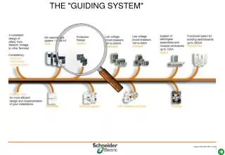
THE "GUIDING SYSTEM"
THE "GUIDING SYSTEM". Sepam series 80: intelligent solutions for personalized applications. Sepam series 40: high-performing solutions for demanding applications. Sepam series 20: simple solutions for common applications. Sepam protection relays.

THE "GUIDING SYSTEM"
E N D
Presentation Transcript
Sepam series 80: intelligent solutions for personalized applications Sepam series 40: high-performing solutions for demanding applications Sepam series 20: simple solutions for common applications Sepam protection relays A range of solutions for all applications Sepam series 10: designed for building and Utilities
Sepam Series 10 selection guide • Sepam series 10 N: earth fault protection • Sepam series 10 B: 3 phases overcurrent and earth fault protection • - Sepam series 10 A: communication, logic input and signalling relays
Specific protection sensors Sub station transformer generator Bus bar capacitor motor B 80 S 80 S 20 T 20 M 20 Series 20 T 81 M 81 3I + I0 S 81 10 I / 8 O 1 com. port S 23 50BF T 23 S 82 G 82 T 82 B 21 S 84 3 V + V0 B 22 81R Series 40 S 40 T 40 G 40 3I + I0 10 I / 8 O 1 com. port Logical equations 3V S 41 67N M 41 S 42 T 42 67et 67N Series 80 3I + 2xI0 3V + V0 42 I / 23 O 2 com. port Logical equations LOGIPAM 67N 67et 67N 37P et 81R T 87 G 88 M 88 2x3I + 2xI0 87 T 3 V + V0 M 87 G 87 87 M B 83 3I + 2xI0 2x3V + V0 C 86 3I + I0 4unbalance I 3V + V0 Sepam series 20 40 80 selection guide
Tools Get to know the Sepam range Tools
Data sheets To be included with quotes Project managers Series 20 Series 40 Series 80 • Description of the main characteristics: • Selection table • Wiring diagrams • Modularity principle
Commercial catalogue Used to choose and order the right Sepam Series 10
Commercial catalogue Used to choose and order the right Sepam Sales engineers 1 Selection guide 2 & 3 for each series • General presentation and selection table • Concise description of metering, protection, control logic and communication functions. • Wiring diagram and general characteristics 4 Add-on modules and accessories • Characteristics • Connection 5 Order forms Series 20 Series 40 Series 80
User manuals Provide the information required to use Sepam Series 20 and 40 Series 10
User manuals Provide the information required to use Sepam Series 20 and 40 Design offices and users • Describe function characteristics in detail • metering • protection • control and monitoring • Present Modbus communication tables • Present characteristics and wiring rules for Sepam and remote modules Series 20 Series 40
User manuals Provide the information required to use Sepam Series 80 Design offices and users • Manual 1 Describes characteristics and wiring rules for Sepam and remote modules • Manual 2 Describes function characteristics in detail • metering • protection • control and monitoring • Manual 3 Presents Modbus communication tables Series 80
DNP3 communication Provides the information required to implement the DNP3 protocol Design offices and users • Presentation of the protocol • List of data • Configuration of interfaces Series 20 Series 40 Series 80
IEC 60870-5-103 communication Provides the information required to implement the IEC 60870-5-103 protocol Design offices and users • Presentation of the protocol • List of data • Configuration of interfaces Series 20 Series 40 Series 80
General introduction Get to know the Sepam range General introduction
Basic earth-fault relay and / or overcurrent Series 10 Different type of supply Standard input (for conventional CTs) Sensitive input (for conventional CTs) Very sensitive (for G0110 CSH 120/200)
No modularity choose the right reference Series 10
How to built the reference Series 10
Choose the base • SEPAM is provided with different types of base : Series 20 Series 40 Series 80
Ready to use configuration • Build your SEPAM configuration : Series 20 Series 40 Series 80 • Choose the base unit e.g. : Then add • connectors : • Application : • Working language : • Manuals :
Current sensor inputs • CCA630 connector • The CCA630 connector is used to connect 3 phase current transformers to Sepam • contain interposing ring CTs with through primaries • Can be disconnected with the power on since disconnection does not open the CT secondary circuit. Series 20 Series 40 Series 80
Current sensor inputs • CCA634 connector • The CCA634 adds an input for a residual current transformer : do not connect a core balance ct do not use base’s Io input • contain interposing ring CTs with through primaries • can be disconnected with the power on since disconnection does not open the CT secondary circuit. Series 20 Series 40 Series 80
Evolve with the installation • Upgrading of functions by optional modules • possible at any time • easy to connect • implementation by simple parameter setting Series 20 Series 40 Series 80
Increase input/output capacity ModuleMES 114 Series 20 Series 40 • Addition of a module with • 10 logic inputs • 4 output relays • 3 models of modules • MES 114 voltage on inputs • 24 to 250 V DC • MES 114 Evoltage on inputs • 110 to 250 V DC • 110 V AC • MES 114 F voltage on inputs • 220 to 250 V DC • 220 to 240 V AC • How to choice : - general case, without immunity constraint Vcc: MES114 - auxiliary supply : 100 or 110V Vcc ou Vca MES114E - auxiliary supply >200V Vcc ou Vca MES114F
Addition of modules with 14 logic inputs 6 output relays 3 models of modules MES 120voltage on inputs 24 to 250 V DC MES 120 Gvoltage on inputs 220 to 250 V DC MES 120 Hvoltage on inputs 110 to 250 V DC 3 modules maximum Maximum configuration: 42 inputs (3 x 14) 23 outputs (3 x 6 + 5) Increase input/output capacity ModuleMES 120 Series 80 • How to choice : - general case, without immunity constraint Vcc MES120 - auxiliary supply 100 or 110V Vcc MES120H - auxiliary supply >200V Vcc MES120G
Remote advanced UMI module Module flush-mounted "wherever you want" May only be connected to a base unit without advanced UMI Improve ergonomics and the installation Series 20 Series 40 Series 80
Remote MET148-2 module Measurement of 8 temperatures By Pt100, Ni100 or Ni120 RTD To protect transformers, motors and generators Number of modules per Sepam Series 20: 1 Series 40: 2 Series 80: 2 Acquire temperature data Series 20 Series 40 Series 80
Remote MSA141 module Choice of measurement via SFT2841 Transmission format 0-10mA 0-20mA 4-20mA 1 module per Sepam Remote measurement available Series 20 Series 40 Series 80
For substation, transformer, generator and busbar applications Measurement of 2 phase-to-neutral or phase-to-phase voltages Checking for voltage, frequency and phase differences between 2 different networks Configuration via base unit 3 output relays to enable coupling used by Sepam to control the closing of breaking devices Enable the coupling of 2 networks Remote MCS025 module Series 80
Connect optional modules • Inter-module connection cables • CCA770, 0.6 m long • CCA772, 2 m long • CCA774, 4 m long • 1 single chain of modules Series 20 Series 40 Base unit Cable 1st module Cable 2nd module Cable 3rd mod. Series 20 CCA772 MSA141 CCA770 MET148-2 CCA774 DSM303 Series 40 CCA772 MSA141 CA770 MET148-2 CCA774 DSM303 Series 40 CCA772 MSA141 CCA770 MET148-2 CCA772 MET148-2 Series 40 CCA772 MET148-2 CCA770 MET148-2 CCA774 DSM303
Connect optional modules • Inter-module connection cables • same as for Series 20 & 40 • CCA785 must be used to connect the MCS025 module (cable supplied with the module) • 2 chains of modules Series 80 Base unit Cable 1st module Cable 2nd module Cable 3rd mod. Chain 1 D1 CCA772 MET148-2 CCA770 MET148-2 CCA774 DSM303 Chain 2 D2 CCA772 MSA141 CCA785 MCS025
Communicate: no interface needed Series 10 • Sepam series 10 can be daisy chained to a RTU (with Modbus or IEC 60870-5-103 protocols • Several functions available for easy remote operation • control of the CB • dated events and trip currents • reading of the currents • reset of the protections to scada system
Modbus interfaces ACE949-2: 2-wire RS 485 ACE959:4-wire RS 485 ACE937: Fiber optic Number of interfaces that can be connected: Series 20: 1 Series 40: 1 Series 80: 2 Communicate: interfaces forconnection to one network Series 20 Series 40 Series 80
ACE969-TP Number of interfaces Series 20: 1 Series 40: 1 Series 80: 2 Communicate: interfaces forconnection to two networks • Interfaces: Series 20 Series 40 Series 80 ACE969-FO network linked to the supervisory system • 2-wire RS 485 • Fiber optic S-LAN • MODBUS, DNP3, IEC 60870-5-103 • 2-wire RS 485 • MODBUS network linked to a PC for Sepam parameter setting E-LAN
S-LAN E-LAN Series 20 Series 40 Series 80 S20 >V0526 S40 >V3.00 S80 : all versions
Software Get to know the Sepam range Software
Selection guide Definition and quoting of Sepam • Selection of protection functions • Selection of remote modules • Basic configuration • Creation of the quote Series 20 Series 40 Series 80
SFT2841 Sepam parameter setting • 2 operating modes • not connected • connected to Sepam • Windows environment • On-line help available • Comes in 3 languages, and may also be customized • For commissioning, the SFT2841 tool is • useful for Series 20 • recommended for Series 40 • essential for Series 80 Series 20 Series 40 Series 80
SFT2826 Display of disturbance recording files • Selection of analog channels displayed • Selection of logic data displayed • 2 cursors to measure differences • Possibility of zooming on a zone of the graph Series 20 Series 40 Series 80
SFTSAV Diagnosis of Sepam operating problems • Display of current and cumulative faults • Display of passwords • This software is not diffused yet. Provided by the help desk where necessary Series 20 Series 40 Series 80 Internal PMC use only
SFT2840 Conversion of language files • Conversion of all text displayed on front panel • Creation of a language file Series 20 Series 40 Series 80
SFT2842 Adaptation of Sepam units in local adaptation centers • Loading of the application in Sepam • Loading of language files in Sepam Series 20 Series 40 Series 80 For local adaptation center
SFT2885 Creation of control logic schemes • Entry of the control logic scheme • Simulation of operation Series 80
SFT2887 Conversion of Sepam 2000 control logic into Sepam Series 80 control logic • Definition of I/O equivalence tables • Conversion of control logic • Generation of a report Series 80
No software Series 10 Sepam series 10 is easy to configure: no need for a PC software
Protection for each type of application Get to know the Sepam range Protection for each type of application
Without voltage monitoring 50/51 : maxi I 50N/51N : maxi I0 46 : unbalance (50BF : breaker failure) • With voltage monitoring 50/51 : maxi I 50N/51N : maxi I0 46 : unbalance 50BF : breaker failure 27 (+D+R) : Under voltage (–positive seq – remanent) 59 +N : Over voltage – neutral displacement 47 : negative sequence over voltage 81L+H : under – over frequency Incomer protection Detection of short-circuits and overloads on busbars • thermal overload for cables 49RMS with a single time constant S81/82/84
Additional bus bar voltage monitoring A single L-L or L-N voltage on the second measuring point for 27+R / 59 / 81 L+H protections • Load-shedding by ROCOF (rate-of-change of frequency) function (81R) • for faster action Incomer protection Detection of short-circuits and overloads on busbars
Directional phase 67 and earth fault 67N/67NC • Directional discrimination • Underpower disconnection function 37P • disconnection of the network if the power drawn by the load can be supplied by the generator • Automatic transfer (AT) • Synchro-check 25 Parallel Incomer protection Isolate the faulty section and resupply when required
Monitoring of bus bar voltages • 27 +D+R : Under voltage –positive seq - remanent • 59 +N : Over voltage – neutral displacement • 47 : negative sequence over voltage • 81L+H : under – over frequency • Load-shedding by ROCOF (rate-of-change of frequency) function (81R) • for faster action Bus bar protection Monitoring of voltages and frequency
Monitoring of the voltages and frequency of two bus bars • 50/51 : maxi I 50N/51N : maxi I0 • 50BF : Breaker failure • 46 : unbalance • 27 +D+R : Under voltage –positive seq - remanent • 59 +N : Over voltage – neutral displacement • 47 : negative sequence over voltage • 81L+H : under – over frequency Coupling circuit breaker protection Detection of short-circuits on bus bars Monitoring of voltages and frequency