1 / 76

The Construction of Vertical Evolution

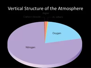
The Construction of Vertical Evolution. Nigel Howe. The Thought Process. June 2006. June 2006. July 2008. Cross Section Drawing with Cutting List. Design Issue. A cross section drawing showing a curve made using regular segmented rings.

Télécharger la présentation

The Construction of Vertical Evolution

An Image/Link below is provided (as is) to download presentation Download Policy: Content on the Website is provided to you AS IS for your information and personal use and may not be sold / licensed / shared on other websites without getting consent from its author. Content is provided to you AS IS for your information and personal use only. Download presentation by click this link. While downloading, if for some reason you are not able to download a presentation, the publisher may have deleted the file from their server. During download, if you can't get a presentation, the file might be deleted by the publisher.

E N D

Presentation Transcript


  1. The Construction of Vertical Evolution Nigel Howe

  2. The Thought Process June 2006 June 2006 July 2008

  3. Cross Section Drawing with Cutting List

  4. Design Issue

  5. A cross section drawing showing a curve made using regular segmented rings

  6. This drawing shows the changes to ring 19 to overcome the “slab” problem.

  7. Flat, Soon to become round

  8. Cutting the planks into 1 ½” planks for segmenting

  9. Running the strips through the thickness planer

  10. Cutting segments on the sled

  11. Hand sanding the glue surface

  12. Five sets of segments ready for the glue table

  13. Cutting the maple strips

  14. Hand sanding the maple strips

  15. A segmented ring dry fitted inside a hose clamp

  16. The segments are aligned as the clamp is tightened

  17. Each ring is held up to a light to check that all joints are tight

  18. The hose clamp is removed and glue is applied

  19. Placed on wax paper the ring is glued and realigned as the hose clamp is tightened

  20. The first ring glued and set aside to dry

  21. A large diameter ring is dry fitted to check the joints

  22. The light test is done large or small

  23. The segments for the 3 top rings were cut oversize, then maple strips were glued to the side of 12 segments, the other 12 are left plain.

  24. All 24 segments are then cut lengthwise. The eraser on the end of an unsharpened pencil make a great non-slip push stick.

  25. All 24 segments of a top ring. 12 with maple, 12 plain. 2 have already been cut.

  26. All 24 segments cut and lined up

  27. The middle strips have traded places

  28. Ready for gluing

  29. Glue is applied. A straight edge is used on the maple edge to insure alignment.

  30. The reassembled segment is then cut to size

  31. All 24 segments glued to make a complete ring

  32. All 63 rings glued! Next step, flatten both sides!

  33. Hot melt glue is used to hold the ring to an MDF face plate for flattening

  34. Mounted and ready to be flattened

  35. ½” bowl gouge makes the first cut

  36. Light cuts with a square scrapper

  37. Close up of scrapper cut. Oh, look! It’s ring 13. Unlucky for some

  38. Sanding the flattened surface

  39. Checking the ring for flatness using a straightedge and a flashlight

  40. One of the larger diameter rings being flattened

  41. All 63 rings flattened

  42. Gluing the rings together begins. You can never have to many clamps!

  43. Another clamping method.

  44. When all the clamps are being used , Improvise !!!

  45. Another use for steel flanges and blinds

  46. 15” diameter faceplate to be glued onto section #1

  47. 15” diameter faceplate being glued to the top of section # 1

  48. The top ½ of section 1 is mounted on the lathe ready to start turning

  49. Starting to shape the underside of section #1. Photo taken without a flash.

  50. Starting to shape the underside of section #1. Photo taken with a flash.

More Related