Download
1 / 21
690 likes | 1.57k Vues
Basics of Mechanical Drawing and Dimensioning. ChE 126 Borrowed mostly from the Fundamentals of Engineering Honors program at Ohio State. How Would You Describe This?. Describe this using only words How effective is it?. Three Basic Types of Technical Drawings. Freehand sketches

E N D
Basics of Mechanical Drawing and Dimensioning ChE 126 Borrowed mostly from the Fundamentals of Engineering Honors program at Ohio State
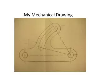
How Would You Describe This? • Describe this using only words • How effective is it?
Three Basic Types of Technical Drawings • Freehand sketches • Instrument drawings • Computer drawings and models
Introduction to Projections • Present 3-D objects with 2-D media • Two Basic Categories OrthographicPictorial
Hidden Lines – represent features that cannot be seen in the current view • Centerlines – represent symmetry and mark the center of circles, the axes of cylinders, and the axes of symmetrical parts, such as bolts Hidden and Center Lines in Orthographic Projections • Object Lines – represent visible features for an object
For Example: 1. Visible 2. Hidden 3. Center
Use very light lines for drawing in the construction lines Step 1 – Lightly Block Three Views
Step 2 – Lightly Block Major Features • Holes • Arcs • Cutouts Use very light lines for drawing in the construction lines
Step 3 – Add Final Lines Use very light lines for drawing in the construction lines
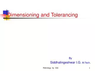
Dimensioning • Orthographic and isometric views define the shape and general features of the object • Dimensioning adds information that specifies • Size of the object • Location of features (e.g. holes) • Characteristics of features (e.g. depth and diameter of hole) • Dimensions also communicate the tolerance (or accuracy) required
Units of Measure Angle Dimensions • Length • English: Inches, unless otherwise stated • Up to 72" • Feet and inches over 72" • SI: millimeter, mm • Angle • degrees, minutes, seconds
Dimensioning Basic Shapes – Assumptions • Perpendicularity • Symmetry
Dimensioning Basic Shapes • Rectangular Prism
ALWAYS give DIAMETER " " for full circles (360 degrees) and RADIUS "R" for arcs (less than 360 degrees) Dimensioning Shows: A) Size B) Location and Orientation
General Guidelines: Clarity is the Goal • Dimension Outside of View Avoid Good Practice
General Dimensioning Guidelines • Start with basic outside dimensions of the object • Height • Width • Depth • Add dimension for location and size of removed features • Add general and specific notes – such as tolerances
Practice Problem How many Dimensions are needed?
Practice Problem How many Dimensions are needed? Answer: 8