Download
1 / 22
220 likes | 332 Vues
Experimental Facilities John Hill EFAC review October 19 th , 2006. Contributors to XFD Portion of CDR. James Ablett Marc Allaire Dieter Schneider Wuxian Shi Vivian Stojanoff Robert Sweet Mark Chance Mike Dudley Paul Northrup Peter Stephens Joe Woicik Sushil Sharma Steve Hulbert

E N D
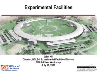
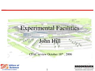
Experimental FacilitiesJohn HillEFAC review October 19th , 2006
Contributors to XFD Portion of CDR James Ablett Marc Allaire Dieter Schneider Wuxian Shi Vivian Stojanoff Robert Sweet Mark Chance Mike Dudley Paul Northrup Peter Stephens Joe Woicik Sushil Sharma Steve Hulbert Toshi Tanabe Sam Krinsky George Rakowsky Anatoly Snigirev* Lisa Miller Elio Vescovo Peter Johnson Lin Yang Qun Shen PK Job Qiong Wu Paul Dumas Scott Coburn Ruben Reininger* Natasha Bozovic Ivan Bozovic Paul O’Connor Sal Pjerov Oliver Hignette* Marc Tricard* Christian Schroer* Chris Jacobsen* Chris Homes Wayne Betts Barrett Clay Bob Delasio Tony Kuczewski Jeff Landgraf Jerome Lauret Dennis Poshka Ivan So Zhijian Yin Roger Dejus Nick Simos Elaine DiMasi Mohan Ramanathan* Thomas Gog* Larry Carr Jorg Maser* Ken Evans-Lutterodt Deming Shu Alfred Baron* Yuri Shvyd’ko* Clement Burns Alec Sandy* Simon Mochrie* Ian Robinson* Dario Arena Cecilia Sanchez-Hanke Lonny Berman Peter Takacs Peter Siddons Christie Nelson Zhong Zhong Harald Reichart * NSLS-II Visitor
Design Specifications Experimental View: • Ultra-high brightness • Drives emittance, energy spread, stability. • High flux • Drives current, top-up, length of straight sections. • Wide spectral range: 0.1 meV to 100 keV • Drives user devices (BM, undulators, SCW), storage ring energy.
Importance of Electron Emittance Horizontal emittance Vertical emittance l=1A Fraction of flux into focused spot = ..and fraction of flux delivered in spot 1 Where and So, aseel 0, etot
Effect of Insertion Device Length E=8.33 keV, 5th harmonic of U19
Effect of b BROOKHAVEN SCIENCE ASSOCIATES To a zeroth approximation, users want the most photons in the smallest spot, with the smallest divergence: Brightness Maximum brightness b=L/2p For L=3m then optimum b=0.5m L=3m e=0.5 nm
Current Parameters bx=2.7m, by=0.95m bx=18.1m, by=3.1m 5m 8m Photon Beam 5m* bx=0.3 m, by=0.95m Size DivergenceSize Divergence Size Divergence Vert. 5.9 mm 12 mrad 5.9 mm 12 mrad 6.3 mm 11.9 mrad Horiz. 14 mm 44 mrad 39 mm 18.6 mrad 100 mm 13 mrad 1st harmonic, 3m U19 * Possible low-beta option Angular acceptance of C(111) bvertical Has minimal impact on photon beam. bhoriz Allows some tuning of photon divergence and beam size
IR from Bending Magnets Extraction of IR from BM appears feasible with good performance down to 1 cm-1 Currently looking into impact on accelerator and cost.
Far-IR performance NSLS-II std gap dipoles NSLS-II large gap dipoles (60 mm) NSLS-II v. large gap dipoles (90 mm)
Beamlines • For the purposes of obtaining a detailed cost estimate and to explore the technical issues for state-of-the-art beamlines at NSLS-II, Five insertion device beamlines were explored in some detail: • Inelastic X-ray Scattering (Hill, Shvyd’ko and Baron) • Hard X-ray Nanoprobe (Gog, Evans-Lutterodt) • Hard X-ray Coherent Scattering (Sandy, Mochrie, Robinson) • Soft x-ray Imaging and Coherent scattering (Sanchez-Hanke, Hulbert, Reinginer) • Soft x-ray resonant scattering and inelastic scattering (Arena, Hulbert, Reinginer) BROOKHAVEN SCIENCE ASSOCIATES
Beamlines • In addition, we have considered a number of other beamlines at a less detailed level: • High magnetic field (Nelson) • High Energy (Zhong) • SAXS (Yang) • IR (Carr) • Imaging (Shen) • Damping Wigglers (Berman) • PX (Berman) • ARPES (Johnson/Vescovo) • Bending Magnet (Berman/Arena) Superconducting Magnet NSLS II Experimental floor
Beamline Development Two principal modes : User groups would form and work with the facility to define the scientific mission and technical requirements for the beamline Beamline Access Teams (BATs) Facility receives funding to design, construct, and operate beamlines. Beamline Development Teams (BDTs) User group receives funding to design, construct, and operate beamline.
Usage of Facility NSLS-II NSLS Type IDs BMs Total IDs BMs Total A IR/UV/soft x-ray spectroscopy 1 11 12 3 7 10 B X-ray spectroscopy 6 3 9 0 9 9 C soft-matter/biophysics scattering 4 0 4 0 8 8 D hard matter/strongly correlated 9 1 10 3 5 8 E powder/single Xtal/high-P/optics 7 3 10 3 8 11 F Imaging/micro-probe 4 5 9 2 7 9 G Macromolecular crystallography 7 0 7 2 8 10 Totals 38 23 61 13 52 65 A strawman beamline distribution was constructed for one possible scenario for a mature facility: Note: This process took into account the expected demand, the existing community and the enhanced NSLS-II capabilities. In this scenario a few IDs and a few BMs remain open.
Canting Configuration Canting angle (half) ex Bare - 2.04 nm 5 x 7m 0 0.55 nm 5 x (3.5m + 3.5m) 1.5 mrad 0.71 nm 5 x (3.5m + 3.5m) 2.5 mrad 0.80 nm 5 x (2.33m+2.33m+2.33m) 1 mrad 0.57 nm 5 x (2.33m+2.33m+2.33m) 3 mrad 0.80 nm 8 x 7m 0 0.48 nm 8 x (3.5m +3.5m) 1.5 mrad 0.54 nm 35m DW +1 x(1m +1m) 1 mrad 0.54 nm The effects of canting have been studied as far as the impact on dispersion and hence emittance (Bengtsson): Device Wigglers Undulators
R+D Overview • Four areas of proposed focus: • 1) 1nm Spatial Resolution • Multi-layer Laue approach • Kinoform approach • 2) 0.1 meV Energy Resolution • Asymmetric optics • 3) Reflective Optics Metrology • Optical metrology • At wavelength testing • 4) Detectors • Large area pixelated detectors • Integrated electronics
Tentative Process & Schedule 2007 2008 2009 2010 2011 2012 2013 2014 2015 Full proposal CDR TDR CDR TDR Construction Commiss- ioning LOI: Select BATs Project BATs TDR LOI: Select BDTs Construction Commiss- ioning Initial BDTs Possible MIEs ? Possible MIEs BO Ring bldg 1st beam
Remainder of the Talks • Today • Conventional Facilities- Marty Fallier • Beamline Development – Hill • Tomorrow • Beamlines • Hard x-ray undulator beamlines – Hill • Soft x-ray undulator beamlines – Steve Hulbert • Damping Wiggler and BM beamlines – Lonny Berman • IR beamlines – Larry Carr • Cost Estimate/Trust Fund - Hill • R+D • 1nm – Evans-Lutterodt • 0.1 meV – Yuri Shvyd’ko • Detectors – Paul O’Connor • Insertion Devices – Toshi Tanabe • Metrology – Peter Takacs
Summary • XFD portion of CDR is nearing completion. User requirements generated by this have driven accelerator and conventional facilities design. • Conceptual designs have been carried out for a number of beamlines to inform a detailed cost estimate, and a number of others at a pre-conceptual level. • Some beamlines will be built as part of the construction project utilizing a trust fund approach. These will begin commissioning in 2013. • Remaining beamlines will be built with other funds (e.g. will pursue potential MIEs and other non-BES funds) and brought online in the following years. • Items requiring R+D have been identified and a plan outlined. • User Access modes and facility build-out issues have begun to be addressed.