Experimental Facilities
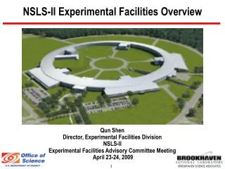
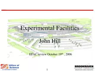
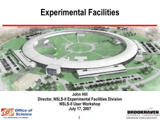
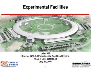
Experimental Facilities. John Hill Director, NSLS-II Experimental Facilities Division NSLS-II User Workshop July 17, 2007. Novel features of Design. The DBA-30 design has a number of novel features that offer a unique range of opportunities for our large, diverse community of users:

Experimental Facilities
E N D
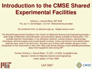
Presentation Transcript
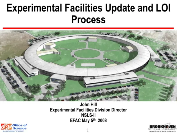
Experimental Facilities John Hill Director, NSLS-II Experimental Facilities Division NSLS-II User Workshop July 17, 2007
Novel features of Design The DBA-30 design has a number of novel features that offer a unique range of opportunities for our large, diverse community of users: Low emittance Ultra-high flux and brightness soft x-ray and High current, hard x-ray undulator sources long straights Damping wigglers Very intense broad band sources of hard x-rays Soft Bends Bright sources of soft x-rays Large gaps to provide excellent far-IR source. 3 Pole Wigglers High-flux, bright sources of hard x-rays
Three-pole Wigglers Added to provide hard x-ray dipoles without big impact on the emittance. 2 mrad source Each BM port can either be a soft bend or a 3PW source ~15 3PWs would increase the emittance ~ 10%
Radiation Sources: Infra-Red Standard gap BMs provide excellent mid and near IR sources Large gap (90 mm) BMs provide excellent far-IR sources
Electron Beam Size Truly tiny electron beams…
Heat Load Calculations Undulator Maximum thermal slope error in beam footprint = ±4 µrad (cf Darwin width of 31 mrad) Calculations for worst case U14 superconducting undulator: 2σ beam, Total power = 92 W (filtered) Wiggler Power from the insertion devices is large, but it can be handled Maximum thermal slope error in beam footprint = ± 23 µrad Calculations for L=7m damping wiggler: 0.25 mrad, Total power = 1.8 kW (unfiltered)
Experimental Floor BROOKHAVEN SCIENCE ASSOCIATES • 1 pentant (= 6 sectors) served by 1 LOB: • 72 offices • 6 labs (480 sf) • Vibration studies (FEA) carried out to minimize sources and propagation of vibrations from ground up. • Long beamlines would have hutches outside the experimental hall.
Vibration Suppression at NSLS-II • Extensive FEA modeling of vibrations in facility underway (N. Simos) • Goal is to: • Understand site • Mitigate external and internal sources • Isolate sensitive beamlines Studies indicate that cultural noise will be trapped by the floor Service Bldg Possible solutions: slab thickening, isolation joints, trenches…
NSLS-II Beamlines • 15 low-b straights for user undulators • Could potentially drive up to 30 beamlines by canting two undulators • 4 high-b straights for user undulators • Could potentially drive up to 8 beamlines by canting two undulators • 8 high-b straights for user damping wigglers • Could potentially drive up to 16 beamlines by canting two DWs • 27 BM ports for UV and soft X-rays • Up to 15 of these can have 3-pole wigglers to provide hard x-rays. • 4 large gap BM ports for far-IR At least 58 beamlines More w/ multiple IDs per straight Multiple hutches per beamline are also possible
Project Beamlines • Project goal: To provide a minimum suite of insertion device beamlines to meet physical science needs that both exploit the unique capabilities of the NSLS-II source and provide work horse instruments for large user capacity. • The beamlines are: • Inelastic x-ray scattering (0.1 meV) • Nanoprobe (1 nm) • Soft x-ray coherent scattering and imaging • Hard x-ray coherent scattering and SAXS • Powder diffraction (damping wiggler source) • EXAFS (damping wiggler source)
Nanoprobe • Mission • Nanoscience: hard-matter • Imaging, diffraction • Capabilities • 1nm, short working distance • 10nm, larger working distance • Possible remote hutch • Source • U19 in lo-b straight* • *A candidate for extended straight. 1 nm 10 nm
Inelastic X-ray Scattering • Mission • Low energy modes in soft matter • Phonons in small samples (Hi-P, single crystal..) • Capabilities • 0.1 meV, fixed energy • 1.0 meV, fixed energy • Source • U19 in lo-b straight* • *A candidate for extended straight. 0.1 meV 1.0 meV
Hard X-ray Coherent Scattering • Mission • Slow dynamics in soft matter • Nanoscale imaging of hard matter • time-resolved SAXS (biological processes) • Capabilities • XPCS/SAXS • Coherent Diffraction • Source • U19 in hi-b straight* • *gap > 7mm Coherent Diffraction/SAXS XPCS Secondary optics
Soft X-ray Coherent Scattering • Mission • Imaging of bio samples • Hard matter, magnetic systems • Capabilities • Coherent imaging + microspectroscopy • Coherent scattering • Fast switching of polarization • Source • 2 x EPU 45 in lo-b straight (canted at 0.25 mrad)
Powder Diffraction • Mission • Materials Science • time-resolved catalysis • Capabilities • 5-50 keV • Analyser-mode and strip-detector mode • Sample environments (high-P, low-T, high-T..) • Source • 3m damping wiggler in hi-b straight BM hutch Powder-I Powder-II
XAFS Mission Environmental science, catalysis Materials science Capabilities Microprobe In-situ catalysis, controlled atmosphere Source 3m damping wiggler in hi-b straight BM hutch EXAFS-I EXAFS-II
Path Towards 1 nm Kinoforms E-beam at Lucent Etching at BNL (CFN) Refractive optic with minimal absorption • Achieved 82 nm • Theoretical calculations show 1nm is possible • Technical challenge in fabricating multiple lenses with sufficiently smooth walls. s=82 nm Multi-layer Laue Lenses Thin film multilayers, sectioned for use as ZPs • Pioneered at ANL • Achieved 19 nm • Theoretical calculations show that 1nm is possible. • Technical challenge in fabricating thick MLs with atomically smooth layers. s=19 nm
Path Towards 0.1 meV Asymmetric Optics acting as Dispersive Elements • Energy resolution controlled with asymmetry parameter • Achieve high energy resolutions at moderate photon energies (9 keV) DE=2 meV • Technical Challenges: • Fabrication and mounting of large Si crystals • Temperature stability E=9.1 keV Y. Shvyd’ko et al PRL (2006)
Summary • Conceptual design of accelerator has matured into an exciting design, promising superlative experimental capabilities. • World-leading performance extends from the far-IR to the very hard x-ray. A range of sources will be available to match the various scientific needs. • These include unprecedented energy and spatial resolution for hard x-ray beamlines and world-leading resolution and flux for soft x-ray beamlines. • Project insertion device beamlines have been identified. User community to define the scientific mission of these beamlines. • Looking forward to your input and feedback during the workshop.