Download
1 / 28
280 likes | 391 Vues
This presentation outlines design requirements and potential engineering solutions for installing armor on the outboard side of the CHI gap in the NSTX system. The armor aims to mitigate plasma and heat degradation, particularly in the NSTX-Upgrade, where the inner target is narrower. Key features include tolerating thermal loads, preserving diagnostic integrity, and minimizing changes to existing graphite tiles. The goal is to enhance performance stability while maintaining the integrity of the NSTX operation. Proposed next steps and improvements will also be discussed during the session.

E N D
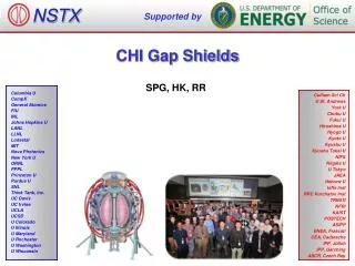
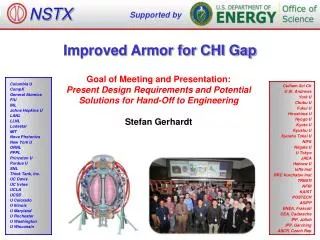
NSTX Supported by Improved Armor for CHI Gap Goal of Meeting and Presentation: Present Design Requirements and Potential Solutions for Hand-Off to Engineering Stefan Gerhardt Columbia U CompX General Atomics FIU INL Johns Hopkins U LANL LLNL Lodestar MIT Nova Photonics New York U ORNL PPPL Princeton U Purdue U SNL Think Tank, Inc. UC Davis UC Irvine UCLA UCSD U Colorado U Illinois U Maryland U Rochester U Washington U Wisconsin Culham Sci Ctr U St. Andrews York U Chubu U Fukui U Hiroshima U Hyogo U Kyoto U Kyushu U Kyushu Tokai U NIFS Niigata U U Tokyo JAEA Hebrew U Ioffe Inst RRC Kurchatov Inst TRINITI NFRI KAIST POSTECH ASIPP ENEA, Frascati CEA, Cadarache IPP, Jülich IPP, Garching ASCR, Czech Rep
Goals • Problem: Plasma & heat entering the CHI gap has been known to • degrade discharge performance due to imperfect PFCs, and • damage diagnostics in the CHI gap, • Problem may be more severe in NSTX-Upgrade, where the horizontal inner target is more narrow. • Goal: Install armor on outboard side of CHI gap. • Graphite is not considered a plausible candidate due to high temperature bake-out requirement. • Provides 2 benefits • For cases with OSP on OBD bull-nose tiles, armor increases tolerance to transient inboard motion of the SP. • For cases with OSP in the inner horizontal target, armor improves power handling of the far(ther) SOL heat flux. • Not planning for this armor to be a primary, “steady-state” power handling component.
Requirements • Solution should cover all plasma facing horizontal stainless steel surfaces on the outer vessel, inboard of the first BBQ rail. • Small stainless fasteners still allowed. • Solution must tolerate loads from 2 MA, 1T disruptions as per NSTX-U GRD. • Solution must tolerate NSTX bakeout. • Solution must not compromise CHI operation. • Solution should not mandate changes to OBD graphite tiles. • Solution should preserve the magnetic flux loops just outboard of the vessel flange. • There should be thermocouples imbedded in some number of the shields. • # of TCs TBD. • Heat fluxes: • Solution should tolerate time average heat load of 3 MW/m2 for 5 seconds. • Should tolerate 0.1 second duration transient loads of 15 MW/m2, every 1 second, with a steady background of 1.5 MW/m2, for a total of 5 seconds. • These requirements can be iterated with physics as necessary. • Should be consistent with cold lithium deposition. • If single point grounded, should be able to take at least 20 kA for total ring (CHI, Halo currents). • Solution should minimize changes to axisymmetric passive currents.
Outline • Pictures of the Gap. • NSTX-U Equilibria. • Heat flux requirement. • Proposed solutions (schematic). • Primitive electromagnetic analysis. • Comment on fasteners and design concepts. • Proposed next steps.
Picture of CHI Gap Bull-node tiles Flux Loop Damaged Sensor (removed during outage due to excessive damage) Vessel Flange Gap was wider than the flange in NSTX. Want this view to show only shields! No stainless flange. No flux loop. No vessel.
Database of Equilibria used to Determine Most Likely Field and Field Line Angles at Shield Location Equilibria from J. Menard All have BT=1.0 T, IP=2.0 MA LSN, DN, SFD, high-delta, low-delta,… Field line angle is with regard to the horizontal surface on the top of the flange. Most have small field line angles. A few outliers…
Cases with Larger Field Line Angle are Typically Well Into the Private Flux Region Field line angle at sensor in red in center of equilibrium
Cases of Concern Typically Have Small Field Line Angles Less Than 7 Degrees (I) 0.5 cm flux lines in red
Cases of Concern Typically Have Small Field Line Angles Less Than 7 Degrees (II) 0.5 cm flux lines in red
Cases of Concern Typically Have Small Field Line Angles Less Than 7 Degrees (III) 0.5 cm flux lines in red
Heat Loading Requirement From NSTX Data and IP Scaling, Assuming Similar Flux Expansion • Steady-state heat flux requirements: • Assume that the radial distribution of heat is similar in form to NSTX cases. • Drops by a factor of 2 in 5cm at 800 kA-> l0=0.05/log(2)=0.072 • Take a configuration with the OSP 8 cm inboard of the CHI gap. • Heat Flux @ 1.2 MA, 12 MW, Qpk=20 MW/m2:~3 MW/m2 steady state is required • Transient heat flux requirements • Come from instances where the OSP is on the bullnose tiles, transiently drifts in. • Assume a steady heat flux of 1.5 MW/m2. • Add a 0.1 seconds transient at 15 MW/m2, every second. • Time average power is 1.5+0.1*15=3 MW/m2 4th Quarter JRT Report
CHI Gap is More Narrow in the Upgrade Gap Flange
Propose to Put a “Cap” on the Main Vessel Flange Vessel Top Vessel Bottom
Concept #1 Was For a Small # Solid Moly Arcs Arc to be bolted directly to flange. Needed to look at changes to the aggregate vessel resistivity
Substantial Modification to Local Vessel Resistivity With Bulk Molybdenum Shields Gap Gap Shields • Compute the toroidal resistance of local conductors vs. gap between shields and # of shields. • Molybdenum has low resistivity. • hSS= 7x10⁻⁷Wm • hMo= 5.5x10⁻⁸Wm • hCu= 1.7x10⁻⁸Wm • Molybdenum shields reduce local resistivity by a factor of ~3 if not isolated from vessel. • Like a 2” by .2” copper ring inside the vessel. Vessel Flange Full flange Section of Vessel 2” Wide Vessel Wall Toroidal Angle Solid: Moly. Shields Dashed: Bulk Stainless Shields
Concept #2 Thins the Moly & Uses Grafoil Pads • Grafoil has higher resistivity. • hSS= 7x10⁻⁷Wm • hMo= 5.5x10⁻⁸Wm • hCu= 1.7x10⁻⁸Wm • hgrafoil~ 4x10⁻⁶Wm • Use 1 mm thick grafoil sheet. • 1”x1” pad has resistance of 6.4x10⁻⁶W. • 60 of them have resistance of 0.35 mW • Can be trivially cut using a simple template and scissors or razor.
Thinned Tiles and Grafoil Shims Largely Eliminate the Low Resistance Problem Shields Shields • Compute the toroidal resistance of local conductors vs. gap between shields and # of shields. • Take an average height of 0.6*0.5”=0.33” and insert pads at each end. • 3.5 degree electrical gap between shields. • Local toroidal resistance drops from 0.62W to 0.5W. • May not need to isolate the bolts. • Rbolt=72mWcm*0.4cm/(p*0.3cm*0.3cm)=100 mW • This in parallel with the 6.4 mWgrafoil pad. • But it might be good to put an insulating sleeve in to maintain the full 0.4 cm. Vessel Flange Full flange Section of Vessel 2” Wide Vessel Wall Toroidal Angle Solid: Moly. Shields Dashed: Bulk Stainless Shields
Consider Using Coatings to Solve Electrical Problems • Coating on top or bottom: • Molybdenum or tungsten sprayed on top of solid shields. • Bulk shields could be from inconel or stainless. • Electrically insulating coating on bottom of tile. • Alumina coating on bottom of tile. • Substantial difference in thermal expansion coefficients between resistive base metals and refractory coating metals. • aMo=5.3x10⁻⁶m/mK • aW=4.3x10⁻⁶m/mK • aSS=16.0x10⁻⁶m/mK • aInconel=12.6x10⁻⁶m/mK • aalumina=5.4x10⁻⁶m/mK • Alumina and molybdenum have very similar expansion coefficents. • Molybdenum and stainless weigh a similar amount. • This for 0.5x2” cross section.
Concept #3 Uses Solid Molybdenum Shields With Alumina Under-Coatings. • Use solid molybdenum • Use cross-section like concept #1 • 30 pieces/tiles. • 12 degrees per tile • Coat the bottoms with alumina. • R. Ellis has lots of experience with alumina coating on SS, didn’t think that coating Moly would be an issue. • A&A Ceramics, White Engineering. • Stainless fasteners could be used to limit the current. • Rbolt=72mWcm*0.4cm/(p*0.3cm*0.3cm)=100 mW • Rtot= 60*0.0001mW = 6mW • Possibly sleeve them to ensure the full 0.4 cm length. • Will still leave ~5/(0.006+0.002)~600A flowing through bolts during disruption. • May want to isolate 1 side to eliminate the current entirely. • Use a sheet of grafoil mainly for mechanical reasons. • Provide compliance, protect the coating. • Also provides some extra resistance if the coating is compromised.
Circulating Currents Yield a BTxmz Torque About a Radial Axis (I) • Estimate the inductance and resistance based on the boundary of the tile. • Assume that the most important current flows in a single large circulation. • L/R time of ~0.5-1 msec for molybdenum, and ~0.1 msec for bulk stainless • Solve for time evolution of currents for a specified dB/dt Inductive Limit Resistive Limit Intermediate Solve ODE and find maximum current Does not take into account coupling to other components.
Circulating Currents Yield a BTxmz Torque About a Radial Axis (II) • Calculate torques and forces as a function of the # of Moly segments. • Height of 0.5” (concept 1 & 3) • Height of 0.33” (concept 2) • L/R times are neither purely inductive nor resistive. • Torques decrease as the # of segments is increased. • Forces on the end are more constant. • From Force=Torque/Length • Concept #2 has ~500 lbs. • Concept #3 has 700-800 lbs.
Current Quench Leads to Axisymmetric Force • Fast 700 kA disruption leads to ~1.0 V from loops near CHI gap. • Add a factor of 2 safety margin, and then scale by 2.0/0.7~3 for NSTX-U • Result is 6 V • Assume a conservative radial/vertical field of 0.5 T. • Color code: • Red: Solid moly bolted to the vessel flange • Blue: Thinned molybdenum with grafoil spacers, called concept #2. • Concept #3 has a negligible force from axisymmetric effects if the isolation is maintained and bolts are isolated.
Finalizing Fastener Design Part of Engineering Scope • Welded ¼-20 studs appear to have enough strength: • 316 Stainless Steel, ¼-20 threaded rod from McMaster • min. tensile strength of 70,000 psi. • Diameter of 0.2” yields strength of 2200 lbs. • Factor of 2 safety margin yields 1000 lbs. • Properly done stud welding has the bolt fail before the weld. • Do not want to have field lines striking stainless fasteners. • Assume an 8 degree field line. • Welded stud and counter-sunk nut may be workable. • Engineering should assess whether: • there are T-bar/Dovetail like solutions for fasteners. • the fasteners can/should electrically isolate the shields. • Insulators must be compatible with Li deposition 8.1 degrees
Candidate Solutions • Concept #1: Small # of molybdenum shields bolted to flange. • Good: Simplest mechanical solution of all. Possibly best power handling. • Bad: Significant modifications to the conducting structure. Large disruption loads. • Concept #2: Thinned molybdenum shields with grafoil spacers. • Good: Mechanically simple, reduced disruption load and small changes to net conductivity. • Bad: More machining on the molybdenum shields themselves • Concept #3: Solid molybdenum shields with alumina coating and grafoil sheets on back side for electrical isolation. • Good: Mechanically simple, reduced disruption load and small changes to net conductivity. • Bad: May need to isolate fasteners. Less experience with these coatings. • Concept #4: Solid stainless steel or inconel shields w/ molybdenum or tungsten coatings on plasma facing side. • Good: Simple installation, low disruption loading, minimal changes to electrical configuration. • Bad: Potential issues with cyclic thermal stress and flaking, especially with plasma heat to the front face.
Candidate Solutions • Concept #1: Small # of molybdenum shields bolted to flange. • Good: Simplest mechanical solution of all. Possibly best power handling. • Bad: Significant modifications to the conducting structure. Large disruption loads. • Concept #2: Thinned molybdenum shields with grafoil spacers. • Good: Mechanically simple, reduced disruption load and small changes to net conductivity. • Bad: More machining on the molybdenum shields themselves • Concept #3: Solid molybdenum shields with alumina coating and grafoil sheets on back side for electrical isolation. • Good: Mechanically simple, reduced disruption load and small changes to net conductivity. • Bad: May need to isolate fasteners. Less experience with these coatings. • Concept #4: Solid stainless steel or inconel shields w/ molybdenum or tungsten coatings on plasma facing side. • Good: Simple installation, low disruption loading, minimal changes to electrical configuration. • Bad: Potential issues with cyclic thermal stress and flaking, especially with plasma heat to the front face. • Concepts #1 and #4 are much less desirable. • Heat flux and thermal analysis can probably help determine which of #2 or #3 is better.
Recommendations For Near Term (assuming the project wants to do this). • Need an engineer to be assigned. • We should test the mechanical stability of alumina coatings on molybdenum. • Disruption analysis should be checked by engineering. • Thermal analysis needs to be done. • Will the more complicated mechanical structure of the thinned tile create local thermal stresses. • Will the alumina coating provide an unacceptable barrier to the heat leaving the tile. • Probably not…k=30 W/mK for Al2O3, compared to 138 for molybdenum and 16 for stainless steel. • Finish determination of fasteners. • For reducing the modifications to the conducting structures, neither concept really required the fasteners be isolated as long as current is forced through ~0.5 cm of the ¼-20 bolt/stud. • But concept #3 may want them isolated to avoid damaging currents in the bolts/studs themselves. • Need to assess if a T-bar or dove-tail solution exists. • Allows studs/nuts to be welded in vessel at convenient time.