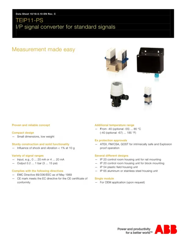
Download
1 / 19
210 likes | 446 Vues
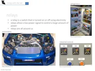
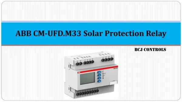
The ABB CM-UFD.M33 is a monitoring relay with multifunctioning grid feeding. It is able to trip the section switch connected between the distributed generation and the public grid allowing the distributed generation to disconnect in case of problems, faults, or grid maintenance. Visit us for more details: http://bcjcontrols.com.au/

E N D
ABB CM-UFD.M33 Solar Protection Relay BCJ Controls
Description: • The ABB CM-UFD.M33 is a multifunctioning grid feeding monitoring relay. It trips the section switch that is connected between the distributed generation and the public grid allowing the distributed generation to disconnect in case of problems (e.g. unstable grid), faults, or grid maintenance. • The device provides different monitoring services to detect 10-minutes average overvoltage, real time over- and under-voltage as well as over- and under-frequency. Additionally, monitoring of vector shift and ROCOF (rate of change of frequency) can be configured to trip the generation in a case of loss of mains.
ABB CM-UFD.M33 Characteristics • Monitoring of voltage and frequency in single-phase and three-phase mains (2-wire, 3-wire or 4-wire AC systems). • Over- and under-voltage, 10-minutes average value as well as over- and under-frequency monitoring. • Two-level threshold settings for over-/under-voltage and over-/under-frequency. • ROCOF monitoring and vector shift detection are configurable. • Interrupted neutral detection. • Default settings in accordance with Great Britain Engineering Recommendations G59/3 and G83/2
ABB CM-UFD.M33 Characteristics • True RMS measuring principle • All threshold values and tripping delays are adjustable • Error memory for up to 99 entries (incl. cause of error, measured value, relative timestamp) • Password setting protection • 3 control inputs (e.g. for feedback signal, remote trip) • 3 c/o (SPDT) contacts • Multiline, backlit LCD display
ABB CM-UFD.M33 Application • The ABB CM-UFD.M33 is a grid feeding monitoring relay that monitors the voltage and the frequency of the public low or medium voltage grid. Whenever measured values are not within the range of adjusted threshold values, the ABB CM-UFD.M33 causes the section switch to trip (consisting of 1 or 2 switching devices according to the applicable standard). This tripping disconnects the power generation of systems such as photovoltaic systems, wind turbines, and block-type thermal power stations from the grid. The fault is indicated by a LED and the corresponding plain text failure message is displayed.
Operating Mode • The ABB CM-UFD.M33 can be set up to monitor single-phase and three-phase mains (2-wire, 3-wire as well as 4-wire AC systems). The unit is configurable by front-facing push-buttons. A display with the corresponding menu enables the selection of preset settings as well as the precise adjustment of the various threshold values and corresponding time delays. Furthermore, the display portrays the measured values clearly. Along with the front-facing LEDs, it shows all information about operational states of output relays and control inputs.
Operating Mode • The ABB CM-UFD.M33 provides three output relays and three control inputs. Output relays R1 (1115-1216/1418) and R2 (2125-2226/2428) are needed for disconnection of a distributed generation system from the public grid. The corresponding feedback signals from the external contacts are monitored using the control inputs Y1-Y0 and Y2-Y0. The third output relay R3 (3135-3236/3438) can be used for to command the close of a motor drive for circuit breaker or as signalization of output relays R1 and R2. The additional control input Y3-Y0 allows tripping of the grid feeding monitoring relay remotely. With control input Y3-Y0 it is possible to suppress both input Y1-Y0 and input Y2-Y0 or the vector shift detection.
Protective Functions • If control supply voltage is applied, then all phases are present and the switch-on conditions for voltages and frequency are fulfilled. Output relays R1 and R2 energize synchronously after the altered switch-on delay. The green LED U/T flashes during timing and becomes steady when the switch-on delay is complete. If a measured value is above or below the set threshold value (overvoltage, under-voltage, over-frequency, under-frequency, ROCOF or vector shift), R1 and R2 de-energize after the altered tripping delay. As soon as the value returns to the tolerance range – taking into account an adjustable hysteresis – and all further switch-on conditions are fulfilled, R1 and R2 re-energize. The fault is indicated by the red LED F and the type of fault is shown in plain text on the display. The event that caused the relay to trip is recorded in the event list. The green LED U/T flashes during timing and turns steady when the delay is complete.
Output Relay R3 (3135-3236/3438) • Output relay R3 can be used to command the closing of a breaker motor. For this function, either of the working principles “closed-circuit” or “open-circuit” must be selected. When output relays R1 and R2 energize, the altered ON-delay starts. When the timing is finished, R3 will be activated for the ON-time duration or until R1 and R2 de-energize. Additionally, R3 can be configured as either “synchronous with R1/R2” or “disabled”. For these two configurations, the ON-delay and the ON-time settings have no influence on the operating function.
Control inputs Y1-Y0, Y2-Y0 • The control inputs, Y1-Y0 and Y2-Y0, are used as feedback contacts for the two switching devices of the section switch. The current status for the switching devices is monitored by the grid feeding monitoring relay. The control inputs configuration for the working principle can be set as “normally closed”, “normally open”, “auto detection”, or completely “disabled”. A failure in the feedback loop has to be manually removed on the device. Please note: 1. “Normally” here refers to “good status” of the grid, this is when all the monitored voltages and the frequency stay within set threshold values and the output relays R1 and R2 are energized. 2. The grid feeding standards vary for different countries.
Control inputs Y1-Y0, Y2-Y0 • Some require that a section switch consists of two independent switching devices, while others only require one switching device working as a section switch. In addition, monitoring of the switching devices by the feedback monitoring is not required by all standards. For this reason, the monitoring functions of control inputs Y1-Y0 and Y2-Y0 are disabled by default. They can be enabled manually in the menu. The function of control input Y3-Y0 can be configured as “remote trip”, “suppress Y1”, “suppress Y2”, “suppress Y1/Y2”, or “suppress vector shift detection”. The working principle of the control input can be configured as “normally open”, “normally closed”, or completely “disabled”.
Control inputs Y1-Y0, Y2-Y0 • Remote trip: With Y3-Y0 configured as “normally closed”, output relays R1 and R2 de-energize if Y3-Y0 is open, and vice versa.Suppress Y1, suppress Y2, suppress Y1/Y2: These functions can be used to suppress evaluation of the chosen feedback loop during generator synchronization, so that the status of the feedback signal won’t be considered a feedback error. A different solution is to make the release window of the corresponding feedback loop larger than the possible duration of synchronization process.
ROCOF (Rate of Change of Frequency df/dt) • Output relay R3 can be used to command the closing of a breaker motor. For this function, either of the working principles “closed-circuit” or “open-circuit” must be selected. When output relays R1 and R2 energize, the altered ON-delay starts. When the timing is finished, R3 will be activated for the ON-time duration or until R1 and R2 de-energize. Additionally, R3 can be configured as either “synchronous with R1/R2” or “disabled”. For these two configurations, the ON-delay and the ON-time settings have no influence on the operating function.
Vector Shift Detection • This function is another possible way of detecting a loss of mains (islanding). The vector shift detection is enabled by default and can be disabled manually in the menu. Through zero crossings, the device detects the vector shift of mains voltage and de-energizes output relays R1 and R2 instantly if the shift exceeds the adjusted threshold value (e.g. 12 °). Only after the set error time will the switch-on conditions be evaluated in order to start an auto re-connection.
Switch-On Conditions • In order to turn on the section switch after applying control supply voltage or after a fault, the voltages and the frequency must stay within the set switch-on conditions during the switch-on delay. This window of voltage and frequency can be restricted more in the menu “Switch-on conditions”. If one parameter exits the window, the switch-on process is interrupted. When all parameters fulfill the switch-on conditions again, the switch-on delay restarts. When the switch-on time is finished, relays R1 and R2 re-energize automatically. If the function “Short interruption” is enabled in the menu “Switch-on conditions” -> “Switch-on delay”, the switch-on delay will be reduced to 5 s in case of an interruption of less than 3 s.
Interrupted Neutral Detection • Interrupted neutral detection is active whenever one of the phase-neutral measuring principles is selected in the menu “Nominal voltage”. The interruption of the neutral conductor will result in an instant tripping of the output relays R1 and R2. Automatic Reconnecting Attempts • If an error occurs at feedback loop Y1-Y0 or Y2-Y0 (e.g. under-voltage release because of a lightning strike), between zero and three automatic reconnecting attempts will be carried out, accounting for the switch-on conditions. Therefore a temporary feedback error doesn’t need to be handled manually. The corresponding error in the feedback loop is stored in the error list.
Test Function • The test function can be used to simulate an error in the installation, so that the time delays of the feedback loops can be determined. A feedback loop includes the output relay, the corresponding switching device, and the feedback contact. The test function can be started by pressing the ESC button for 3 s. The output relays R1 and R2 de-energize immediately and the ABB CM-UFD.M33 gets feedback signals from the section switch through control inputs Y1-Y0 and Y2-Y0 respectively. The time intervals from de-energizing both output relays to receiving both feedback signals is displayed. The menu is returned to by confirming with the OK button.
BCJ Controls – Protection Relays Specialist • When you have a large solar system connecting to the grid, the utility requires special precautions to keep the grid safe. For that you need a 'Grid Protection System' - it is what stands between your solar system and the electricity grid. BCJ Controls helps solar installers navigate the grid connection process to get the system on-line. • We start by supplying a design for the Grid Protection System to use to apply to the utility (aka. DNSP) including information about the network protection relay or zero export device.
BCJ Controls http://bcjcontrols.com.au/