Embedded Systems
Embedded Systems. Sourabh Sankule Manoj Gulati Punit Narang. Basics. What is embedded systems ? What is a microcontroller ? uC vs uP ? CMOS-TTL voltage level Clock ? RAM ? FLASH ? EEPROM ? Registers ? 8 bit / 16 bit / 32 bit ? Why AVR ?. Embedded Systems.

Embedded Systems
E N D
Presentation Transcript
Embedded Systems SourabhSankule ManojGulati PunitNarang
Basics • What is embedded systems ? • What is a microcontroller ? uCvsuP ? • CMOS-TTL voltage level • Clock ? RAM ? FLASH ? EEPROM ? Registers ? • 8 bit / 16 bit / 32 bit ? • Why AVR ?
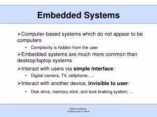
Embedded Systems • Programmable Autonomous System. • Application Specific • Real Time Operation • Long Life ~ 5-10 years and more • Critical System
Layers Software Firmware Hardware
Microcontroller • Programmable Integrated Circuit
Block diagram of uC GPIO RAM Flash ADC/DAC Timers uP Peripherals ROM Interrupts Clock EEPROM UART SPI External / Internal I2C / TWI
RAM int i = 12 : 2 byte char c = ‘c’ : 1 byte Each Peripheral is mapped to certain registers Register Space Variable Space Changing the contents of Registers configures and controls Peripherals 8-bit Registers RAM
FLASH FLASH Memory (Program Memory) .hex File
Why AVR ? • Low cost ~ 300/- • Easy Availability • GCC based Tool-chain support (open source) • World wide university based projects and forums.
Tool-Chain Bunch of utilities which contains following, • Compiler .c .o • Assembler .S / .asm .o • Linker .o .out / .elf • Object Translator .elf/.out .hex • Programmer .hex flash of uC • Debugger For real-time debugging via JTAG • Simulator For simulating
uart.c i2c.S main.c Source Files uart.o lcd.o main.o Object Files main.out / main.elf Project Object File main.hex Final Machine File
Examples • AVRGCC / WinAVR • CVAVR • Bascom
Installations • WinAVR • Notepad++
Using AVRGCC Install WinAVR on your system. Open CMD Prompt type : avr-gcc --help See the manual for more details
WinAVR • AVRGCC : avrlibc • AVRdude programmer
CMD commands ls : list : display folder contents. cd folder_name : change to Folder cd .. : go to parent folder. cd E: change to Drive E mkdirfolder_name: make folder
Sample Code (main.c) #include <avr/io.h> // we are not defining which microcontroller is this ! int main (void){ DDRA =0xFF; PORTA =0xF0; }
1. Compiling avr-gcc-c -mmcu=atmega128 main.c This will create main.o
2. Linking Used when we have multiple source files (.c) avr-gcc -mmcu=atmega128 main.o -o main.out This will generate final object code for the project: main.out
3. Object Copy avr-objcopy -O ihexmain.outmain.hex This will generate Final Intel machine file ready to be loaded to Flash of the microcontroller.
Flash Programming • ISP : in system programming via SPI • JTAG : Joint Test Action Group • HVSP : High Voltage Serial Programmer • Boot-loader via UART
JTAG Circuit AVR JTAG USB/PC JTAG/uC
4. Programmer (AVR-dude) Command line programmer In CMD Prompt type : avrdude for displaying options avrdude -p atmega128 -P com4 -c jtagmkI -U flash:w:main.hex
Makefiles… To reduce the number of steps involved in complete process. Read the Makefile Manual for more details.
First Makefile Create a file in the project folder WITHOUT any extension with following name : Makefile Write Following code main: avr-gccmain.c -mmcu=atmega128 -c avr-gcc -mmcu=atmega128 main.o -o main.out avr-objcopy -O ihexmain.outmain.hex program: avrdude -p atmega128 -P com4 -c jtagmkI -U flash:w:main.hex
Using Makefile Type following on CMD Prompt: make main : will execute commands on label ‘main’ make program : will execute commands on label ‘program’
Completing Makefile PROJ= main # Name of project without extension SRC=main.clcd.cuart.c # List all Source Files here. CC=avr-gcc #Compiler used MCU= atmega128 #Microcontroller used main: $(CC) $(SRC) -mmcu=$(MCU) -c $(CC) -mmcu=$(MCU) *.o -o $(PROJ).out avr-objcopy-O ihex$(PROJ).out $(PROJ).hex program: avrdude-p $(MCU)-P com4 -c jtagmkI -U flash:w:$(PROJ).hex clean: rm*.o *.out *.hex
Auto Generated Makefile Use Mfile generator from WinAVR. Edit following lines, • Line 44 : MCU = atmega128 • Line 65 : F_CPU = 8000000 • Line 73 : TARGET = main • Line 83 : SRC = $(TARGET).c uart.clcd.c • Line 97 : ASRC = i2cmaster.S • Line 276 : AVRDUDE_PROGRAMMER = jtagmkI • Line 279 : AVRDUDE_PORT = com4
IDE : Integrated Development Environment • AVR Studio : backend AVRGCC All tools are inbuilt.
Macros #define LabelReplacement Function through Macros #define add(x,y)(x)+(y)
Shift Operators Right Shift : >> Left Shift : <<
Set Bit REGA Bit Wise OR using | BIT mask To obtain BIT mask Left Shift 1 by 5 times. REGA = REGA | (1 << x) REGA |= (1<<x)
Clear Bit REGA Bit Wise AND using & BIT mask To obtain BIT mask Left Shift 1 by 4 times then take complement. REGA = REGA & ~(1 << x) REGA &= ~(1<<x)
Bit operations on Registers Setting a bit Use the bitwise OR operator (|) to set a bit. REGA |= 1 << x Clearing a bit Use the bitwise AND operator (&) to clear a bit. REGA &= ~(1 << x)
Bit operations on Registers Toggling a bit The XOR operator (^) can be used to toggle a bit. REGA ^= 1 << x; Checking/Reading a bit bit = 1 & (REGA >> x);
3 Registers 8 bit registers mapped to GPIO pins. • PORTX • PINX • DDRX
Link to Group Pins Group-A DDRA Output if Bit set 1 Input if bit set 0
Instruction Binary : DDRA = 0b10101010; Hexadecimal : DDRA = 0xB4; Integer : DDRA = 129;
PORT Example DDRA = 0b11001100; PORTA = 0b10101010;
Example Code for Output Write a program to Blink LEDs in a Serial pattern. LEDs are connected from PA0 to PA5 in Sink Mode ie turns ON on 0V.
PORT Example : Input DDRA = 0b11001100; PORTA = 0b10101010;
PINA Group-A PINA
PINA Example DDRD = 0xF0; PORTD = 0b10100101;
PIN 1 0 Output Input DDRA 0 1 0 1 ON : 3V3 OFF : 0V Tri-State Pull-up PORTA Read Value PINA
Ideal Voltage Range For 0 read : 0V to 1V For 1 Read : 2V to 3V3 Error Range : 1V to 2V