PLL Implementation with Simlink and Matlab
PLL Implementation with Simlink and Matlab. Project 2 ECE283 Fall 2004. Simulink in MATLAB. Graphic user interface Continuous, discrete, and mixed mode Integration with MATLAB Fast prototyping User-defined functions How to run it >>simulink Or click simulink icon. Simulink main screen.

PLL Implementation with Simlink and Matlab
E N D
Presentation Transcript
PLL Implementation with Simlink and Matlab Project 2 ECE283 Fall 2004
Simulink in MATLAB • Graphic user interface • Continuous, discrete, and mixed mode • Integration with MATLAB • Fast prototyping • User-defined functions • How to run it • >>simulink • Or click simulink icon Simulink main screen
Graphic User Interface • Make a new model window • Expand library • Drag and drop • Connect blocks • Simulate • Visualize • Tuning Simulink built-in library
Make a model • New model • Open library • Drag blocks • Connect • Source and sink • Example:AmModEx.mdl Amplitude modulation
Simulation • Tune • Simulation time • Relative tolerance • Refine factor • Etc • Simulate • Example:AmModEx.mdl Simulation parameters
Visualization • Double click scope • Options on signal source and sink • External files • Workspace variables • Example:AmModEx.mdl Simulation output scope
Subsystem • Subsystem for modular programming • How to make it • Subsystem library • Subsystem conversion • Example:AmModEx.mdl Ports and subsystem library Triggered subsystem
Getting Help • Need help? • MATLAB and Simulink help • Mathworks user community • Mathwork technical support Simulink help screen
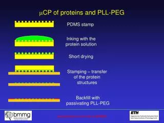
PLL Implementation • Sampler • Voltage controlled clock • Voltage controlled oscillator • Feedback loop Decision-directed phase-locked loop
Sampler • Options • Triggered subsystem • User-defined function • Others • Latched and unlatched • Matters with discrete-time signals • Almost same with continuous-time signals except for feedback • Example:TriggerEx1.mdl • Subsystem examples Latched and unlatched trigger example
Integration • Initiailization • Matched filter • Correlator • External triggering • Example:IntegratorEx.mdl Integration block parameters
S-function • User-defined function written in MATLAB, etc. • One input and one output • scalar, vector, matrix, etc. • Static parameters • R14 provides more options for user-defined function User-defined functions library
S-function Operation • Initialization • Calculate outputs • Update discrete states • Calculate derivatives • Integration • Calculate outputs • Calculate derivatives • MATLAB example code sfuntmpl.mis in matlabroot/toolbox/simulink/blocks S-function operation diagram
Example Code function [sys,x0,str,ts] = VCO(t,x,u,flag,FreqCntr) %VCO switch flag, case 0,% Initialization [sys,x0,str,ts]=VCOInit; case 1,% Derivatives sys=VCODeriv(t,x,u); case 2,% Update sys=VCOUpdate(t,x,u); case 3,% Outputs sys=VCOOutput(t,x,u,FreqCntr); case 4,% GetTimeOfNextVarHit sys=VCPNextHit(t,x,u); case 9,% Terminate sys=VCOExit(t,x,u); otherwise % Unexpected flags End Flag 0: Initialization Flag 1: Calculation of derivatives Flag 2: Update of discrete states Flag 3: Calculation of output Flag 4: Calculation of next sample hit Flag 9: End of simulation tasks
S-function Initialization function [sys,x0,str,ts]=VCOInit sizes = simsizes; sizes.NumContStates = ; sizes.NumDiscStates = ; sizes.NumOutputs = ; sizes.NumInputs = ; sizes.DirFeedthrough = ; sizes.NumSampleTimes = ; % at least one sample time is needed sys = simsizes(sizes); x0 = []; % initialize the initial conditions str = []; % str is always an empty matrix ts = [0 0]; % initialize the array of sample times Define necessary Internal states (continuous and discrete-time) Number of inputs Number of outputs Initial conditions
S-function Output function [sys,x0,str,ts] = VCO(t,x,u,flag,FreqCntr,Phase,Gain) switch flag, …………… case 3,% Outputs …………… sys=VCOOutput(t,x,u,FreqCntr,Phase,Gain); End …………… function sys=VCOOutput(t,x,u,FreqCntr,Phase,Gain) sys = Gain*cos(2*pi*(FreqCntr+u)*t+Phase); T: time X: state U: input Flag: computation mode Static parameters
S-function Instantiation • Drag and drop S-function system block to a model • Double click the block to specify the script name and static parameters • Example: VCOSfuncEx.mdl S-function instance S-function block parameters
Discussions on PLL • Modulation frequency • Number of waves per symbol • Low-pass filter • Simulation length • Symbol feedback delay • Evaluation • Timing error • Capture range • Loop lock range • Effect of symbol error • Effect of signal noise Decision-directed PLL diagram