Download
1 / 21
230 likes | 408 Vues
TE EPC. Power converters implications for Booster Energy Upgrade. Jean-Paul Burnet, Serge Pittet LIU day, 01.12.2010. MPS load characteristic. TE EPC. 16 periods, 4 rings. 1.4 GeV Booster MPS (1/2). TE EPC. TRIM A 1900V 50A pk 30A RMS. Load: 0.5 Ohms / 0.18 H 1.4GeV margins:

E N D
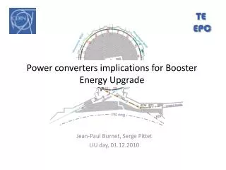
TE EPC Power converters implications for Booster Energy Upgrade Jean-Paul Burnet, Serge Pittet LIU day, 01.12.2010
MPS load characteristic TE EPC 16 periods, 4 rings TE-EPC - Serge Pittet - EDMS 1106116
1.4 GeV Booster MPS (1/2) TE EPC TRIM A 1900V 50Apk 30ARMS Load: 0.5 Ohms / 0.18 H 1.4GeV margins: • MPS voltage: -2% • MPS peak current: -2% • MPS rms current: 3% • TRIM A peak current: 40% • TRIM Q peak current: 0% BHZ Ring 1&4 MPS 3600V 4000Apk 2300ARMS QFO 520V 300Apk 200ARMS QFO Reference magnet GND QDE 520V 300Apk 200ARMS QDE BHZ Ring 2&3 TE-EPC - Serge Pittet - EDMS 1106116
1.4 GeV Booster MPS (2/2) TE EPC • The existing MPS can run faster but cannot provide more peak current • From 4000A to 5500A, the current on the Trim A must be increased by a factor 4 to compensate the Outer rings saturation. % TE-EPC - Serge Pittet - EDMS 1106116
2 GeV Booster MPS TE EPC Upgrade scaling on one cycle • MPS peak current: +30% • MPS rms current: +35% • 18kV apparent power: +77% • 18kV peak power: +45% • TRIM A peak current: +540% • TRIM Q peak current: +40% TRIM A 1900V 270Apk 64 BHZ Ring 1&4 128 QFO Ring 1-4 QFO 520V 420Apk MPS 3600V 5300Apk Reference magnet GND 64 QDE Ring 1-4 QDE 520V 420Apk 64 BHZ Ring 2&3 TE-EPC - Serge Pittet - EDMS 1106116
18kV network TE EPC Fast transients with 2GeV cycle which can not be compensated by Meyrin SVC. 50% increase of active power, 30% increase of reactive power TE-EPC - Serge Pittet - EDMS 1106116
Upgrading existing supply TE EPC • All power components must be upgraded to the new peak current (Thyristors, transformers, filters,…) • Four consecutive 2GeV cycles has to be considered as a DC value for power semiconductors. • Replace the existing TRIM A (+ 1 spare). • Replace the existing QFO and QDE (+1 spare). Side effects: • Major upgrade of magnets cooling circuit needed. • Power DC cables section must be increased. • 18kV average power capability to be checked. • 18kV network will probably not be able to absorb the new peak power pulse. Flickers to be foreseen! TE-EPC - Serge Pittet - EDMS 1106116
“POPS” basic principles TE EPC The energy to be transferred to the magnets is stored in capacitors. • DC/DC converters transfer the power from the storage capacitors to the magnets. • Four flying capacitors banks are not connected directly to the mains. They are charged via the magnets. • Only two AC/DC converters (called chargers) are connected to the mains and supply the losses of the system. Chargers Power to the magnets: +50MW peak Power from the mains 10MW Flying capacitors TE-EPC - Serge Pittet - EDMS 1106116
POPS based proposal (1/2) TE EPC 64 BHZ Rings 1&4 GND Benefits • Overall voltage available increases and would allow a reduction of the RMS current using a faster ramping. • The capacitor bank totally absorbs the peak power on the 18kV network. Meyrin SVC would then become optional. • Spare sharing between MPS A and B and eventually with POPS. • Only a few new cables needed between the reference magnet (BCER) and the MPS. • New B-field regulation to minimize eddy currents and saturation effects impact at higher current and acceleration rate. Drawbacks • Cost estimation 14MCHF using POPS module. • RF acceleration has to be increased. 128 QFO Rings 1,2,3&4 MPS A 2500V 5500A QFO 600V 450A Reference magnet Ring 1&4 Ring 1 B-filed measurement Reference magnet Ring 2&3 Ring 2 B-filed measurement 64 QDE Rings 1,2,3&4 MPS B 2500V 5500A QDE 600V 450A 64 BHZ Rings 2&3 GND TE-EPC - Serge Pittet - EDMS 1106116
POPS based proposal (2/2) TE EPC Upgrade scaling on one cycle • MPS peak current: +30% • MPS rms current: +3% • 18kV apparent power: -26% • 18kV peak power: -78% TE-EPC - Serge Pittet - EDMS 1106116
Layout of new building TE EPC • 420m2 required, only 190m2 available in bdg. 271 ground floor. • Only 200kg/m2 allowed in bdg. 271 first floor. • No space left in bdg. 361. With this new building: • We can install and commission during Booster operation. • We have a backup power supply during the first years. • Easy connection to existing cables and cooling services. New MPSB (2 GeV) (26m x 16m) TT6 TE-EPC - Serge Pittet - EDMS 1106116
Effect of idle cycles TE EPC RMS current can also be reduced keeping RF acceleration used today (3.6kV on the MPS) and providing 2GeV cycles to LHC only: Only 10% RMS current increase if ZERO cycles are inserted. ZERO 12 and 18 would allow a slow setting up of the transfer line: No increase of the RMS current (compared to all cycles at 1.4GeV) if Isolde has no physics during LHC proton filling: TE-EPC - Serge Pittet - EDMS 1106116
Existing supply with idle cycles TE EPC • All power components must be upgraded to the new peak current (Thyristors, transformers, filters,…) • Four consecutive 2GeV cycles has to be considered as a DC value for power semiconductors. • Replace the existing TRIM A (+ 1 spare). • Replace the existing QFO and QDE (+1 spare). Side effects: • Major upgrade of magnets cooling circuit needed. • Power DC cables section must be increased. • 18kV average power capability to be checked. • 18kV network will probably not be able to absorb the new peak power pulse. Flickers to be foreseen! TE-EPC - Serge Pittet - EDMS 1106116
New magnet requirements TE EPC In order to be powered by the existing power supply 4kA/3.6kV, magnet coil copper cross section must increase • By 30% to increase the number of turns and provide the additional field with the MPS rated current. • By 30% to compensate the additional coil length. • By 400% to compensate the increasing inductance (L n2) and keep enough voltage margin for the desired acceleration (U = RI + L dI/dt). Resistive losses divided by 4 but Copper weight multiplied by 7 TE-EPC - Serge Pittet - EDMS 1106116
And what if… (1/2) TE EPC … we increase reasonably the amperes-turns and the section on all magnets: • Existing current rating would be sufficient. • Additional voltage needed to compensate the increasing magnets inductance. • Reactive power still increases and the Meyrin SVC capability would be an issue within 1.2s cycle. • At the end a POPS based supply would be needed. …we increase the amperes-turns and/or the section on the bending only: • Existing supply could be used to power the quadrupoles. • A smaller POPS based supply could be used for the bending magnets. TE-EPC - Serge Pittet - EDMS 1106116
And what if… (2/2) TE EPC …we decrease the magnet gap (and vacuum chamber size) by 30% • Existing power supply can be used. The magnetic cycle would have to be adapted to compensate for the 30% increase in load inductance. …we install a new MPS adapted to the existing magnets and they fail after a few years of operation (they were designed for 0.8GeV). In any cases several MCHF would be saved on the new supply and/or on electricity consumption with new magnets: 15GWh per year at 1.4GeV → 18 MCHF over 25 years 10% increase in current → 21% increase in power → 3.8MCHF TE-EPC - Serge Pittet - EDMS 1106116
Booster Ring (others) TE EPC • Dipoles correctors and multipoles are mainly used at low energy and have enough margin. They will be consolidated during the shutdown 2011-2012. • The Qstrips are only used at injection. Any upgrade would be part of the linac 4 project and not of the Booster energy upgrade. • BDLs are used at ejection but have enough margin. • The DBS are dedicated to destructive beam measurement and will probably not be used at 2GeV. • The shavers are only used at injection. Any upgrade would be part of the linac 4 project and not of the Booster energy upgrade. TE-EPC - Serge Pittet - EDMS 1106116
PSB Ejection TE EPC • BE.SMH: 2GeV setting not exactely defined yet. The capacitor bank size will have to be adapted to provide the additional energy and a new capacitor charger may have to be foreseen. • BE1 to 4.DHZ 11L1, BE1 to 4.DHZ 4L1, BE1 to 4.DVT 11L1 and BE1 to 4.DVT 4L1: Even approaching their rated limits, these converters will not need to be upgraded for 2GeV operation. TE-EPC - Serge Pittet - EDMS 1106116
BT and BTM transfer TE EPC • The transfer line includes some huge bendings (RL load similar to MPS!). An important power transfer is needed for PPM operation. • The BT and BTM transfer lines will have to provide PPM operation between 1GeV or 1.4GeV Isolde and 2GeV PS. • The natural discharge of the magnet is estimated by the current reached after 0.9s starting from 2GeV current. • The capacitor bank size of ALG-1 model will have to be adapted to provide the additional energy. TE-EPC - Serge Pittet - EDMS 1106116
BTP transfer TE EPC • The BTP transfer is not used by Isolde. PS cycles only will go through. • It is a non-PPM only line and quadrupoles should be redesigned for PPM operation, allowing optics flexibility on various beams. TE-EPC - Serge Pittet - EDMS 1106116
EPC Conclusions TE EPC MPS: • The existing supply can not endorse the additional RMS and peak current, even for one single pulse. • An increase of peak power, using traditional thyristor technology, would have a significant negative effect on power quality of the Meyrin network 18 kV. • The solution will probably be a design similar to the new POPS for the PS, using DC capacitors to store the energy for the pulsating load (civil engineering work required, but less demanding on resources, procurement and commissioning). • A higher voltage ratings on each magnet would allow to limit the increasing RMS current, pushing RF acceleration to their limits. Impact of the upgrade on magnets, DC cables, 18kV average power could then be notably reduced. The alternatives would be to reduce Isolde physics program. Transfer lines: • Pulse option must be studied with TE-MSC to reduce the overall RMS current (many magnets could then stay in place). TE-EPC - Serge Pittet - EDMS 1106116