Power Converters
Power Converters. Neil Marks STFC ASTeC /Cockcroft Institute/U. of Liverpool, Daresbury Laboratory, Warrington WA4 4AD, U.K. n.marks@dl.ac.uk. Contents. 1. Requirements. 2 . Basic elements of power supplies. 3 . D.C. supplies: i ) simple rectification with diodes;

Power Converters
E N D
Presentation Transcript
Power Converters Neil Marks STFC ASTeC/Cockcroft Institute/U. of Liverpool, Daresbury Laboratory, Warrington WA4 4AD, U.K. n.marks@dl.ac.uk
Contents • 1. Requirements. • 2. Basic elements of power supplies. • 3. D.C. supplies: • i) simple rectification with diodes; • ii) phase controlled rectifiers; • iii) switch mode systems. • 4. Cycling converters - what do we need: • i) energy storage; • ii) waveform criteria; • 5. So how do we do it: • i) slow cycling accelerators; • ii) medium and fast cycling – inductive storage; • iii) ‘modern’ medium cycling – capacitative storage; • 6. The delay-line mode of resonance.
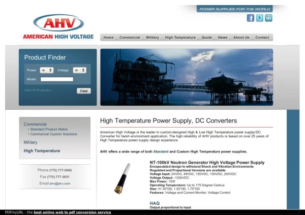
1. Basic Requirements • 1. Typical requirements for d.c. applications (storage rings, cyclotrons, beam-lines, etc.): • smooth dc (ripple < 1:105); • amplitude stability between 1:104 and 1:105; • amplitude adjustment over operating range (often 1:10 ). • 2. Additionally, for accelerating synchrotrons: • energy storage (essential so as not to dissipate stored energy at peak field when ‘resetting’ for next injection) • amplitude control between minimum and maximum current (field); • waveform control (if possible).
regulation (level setting -usually a ‘servo system’) transformer monitoring rectifier LOAD switch-gear smoothing 2 - Basic components. Generic structure of a ‘Power Converter’: feedback control room
Typical components (cont.) • i) switch-gear: • on/off; • protection against over-current/over-voltage/earth leakage etc. • ii) transformer: • changes voltage – ie matches impedance level; • provides essential galvanic isolation load to supply; • three phase or (sometimes 6 or 12 phase); • iii) rectifier/ switch (power electronics): • used in both d.c. and a.c. supplies; • number of different types – see slides 7, 8, 9, 10;
Typical components (cont.) • iv) regulation: • level setting; • stabilisation with high gain servo system; • strongly linked with ‘rectifier’ [item iii) above]; • v) smoothing: • using either a passive or active filter; • vi) monitoring: • for feed-back signal for servo-system; • for monitoring in control room; • for fault detection.
Switches - diodes 10 A; 300 V • conducts in forward direction only; • modern power devices can conduct in ~ 1 ms; • has voltage drop of (< 1 V) when conducting; • hence, dissipates power whilst conducting; • ratings up to many 100s A (average), kVs peak reverse volts. 75 V; 0.15 A 350 A; up to 2.5 kV
- + Switches - thyristors • Withstands forward and reverse volts; • then conducts in the forward direction when the gate is pulsed; • conducts until current drops to zero and reverses ( to ‘clear’ carriers); • after ‘recovery time’, again withstands forward voltage; • switches on in ~ 5 ms (depends on size) – as the forward voltage drops, it dissipates power as current rises; • therefore dI/dt limited during early conduction; • available ratings are 100s A average current, kVs forward and reverse volts.
- + Switches - thyristors
Switches – i.g.b.t. s • The insulated gate bi-polar transistor (i.g.b.t.): 1.2 kV module • gate controls conduction, switching the device on and off; • far faster than thyristor, can operate at 10s of kHz; • dissipates significant power during switching; • is available at ~ 2 kV forward, 100s A average. • will not withstand appreciable reverse volts (a series blocking diode sometimes needed); • will not conduct reverse current(sometimes a parallel reverse ‘free-wheeling’ diode is needed).
3. DC Supplies A single phase full-wave rectifier: + - • Classical ‘full-wave’ circuit: • uncontrolled – no amplitude variation or control; • large ripple – large capacitor smoothing necessary; • only suitable for small loads.
1 period 1 period 1 period 1 period 1 period DC – a 3 phase diode rectifier Three phase transformer • Three phase, six pulse system: • no amplitude control; • much lower ripple (~ 12% of 6thharmonic – 300 Hz) but low-pass filters still needed.
V out V out V out V out Thyristorphase control • Replace diodes with thyristors - amplitude of the output voltageis controlled by retarding the conduction phase: Zero volts output Full conduction – like diode Negative volts output-‘inversion’. Half conduction But current must always be in the forward direction.
Full 12 pulse phasecontrolled circuit. • like all thyristor rectifiers, is ‘line commutated’; • produces 600 Hz ripple (~ 6%) • smoothing filters still needed.
The thyristor rectifier. • The ‘standard’ circuit until recently: • gave good precision (better than 1:103); • inversion protects circuit and load during faults; • has bad power factor with large phase angles (V and I out of phase in ac supply) ; • injected harmonic contamination into load and 50 Hz a.c. distribution system at large phase angles.
Modern d.c. ‘switch-mode’ system. • The i.g.b.t. allows a new, revolutionary system to be used: the ‘switch-mode’ power supply (see your mobile phone charger!):
Mode of operation • incoming a.c. is rectified with diodes to give ‘raw’ d.c.; • the d.c. is ‘chopped’ at high frequency (> 10 kHz) by an inverter/chopper using i.g.b.t.s; • a.c. is transformed to required level; • transformer size is in transformer core)so is much smaller and cheaper at high frequency ; • transformed a.c. is rectified – diodes; • filtered (filter is much smaller at 10 kHz); • regulation is by feed-back to the inverter (much faster, therefore greater stability and faster protection); • response and protection is very fast. Stages of power conversion:
B A Inverter – or ‘Chopper’ The inverter is the heart of the switch-mode supply: The i.g.b.t. s provide full switching flexibility – switching on or off according to external control protocols. Point A: direct voltage source; current can be bidirectional (eg, inductive load, capacitative source). Point B: voltage square wave, bidirectional current.
4. Cycling converters-what do we need to do? • But the required magnetic field (therefore the required magnet current) is unidirectional –acceleration low to high energy: - so ‘normal’ a.c. is inappropriate: We need to raise the magnet current during acceleration - will ‘ordinary’ A.C. do? extraction • only ¼ cycle used; • excess rms current; • high a.c. losses; • high gradient at injection. injection
R LM IM C VM Nature of the Magnet Load Magnet current: IM; Magnet voltage: VM Series inductance: LM; Series resistance: R; Distributed capacitance to earth C.
‘Reactive’ Power and Energy • voltage: VM = R IM + L (d IM/dt); • ‘power’: VM IM = R (IM)2+ L IM(d IM/dt); • stored energy: EM = ½ LM(IM)2; • d EM /dt = L (IM) (d IM/dt); • so VM IM = R (IM )2+ d EM /dt; reactive’ power – alternates between +ve and –ve as field rises and falls; resistive power loss; The challenge of the cyclic power converter is to provide and control the positive and negative flow of energy - energy storage is required.
B/t B Waveform criteria– eddy currents. • Generated by alternating magnetic field cutting a • conducting surface: • eddy current in vac. vessel & magnet; B/t; • eddy currents produce: • negative dipole field - reduces main field magnitude; • sextupole field – affects chromaticity/resonances; • eddy effects proportional (1/B)(dB/dt) – critical at injection.
time Waveform criteria– discontinuous operation • Circulating beam in a storage ring slowly decays • with time – very inconvenient for experimental • users. • Solution – ‘top up mode’– discontinuous operation by the booster synchrotron – beam is only accelerated and • injected once every n booster cycles, to maintain • constant current in the main ring.
Fast and slow cycling accelerators. • ‘Slow cycling’: • repetition rate 0.1 to 1 Hz (typically 0.3 Hz); • large proton accelerators; • ‘Fast cycling’: • repetition rate 10 to 50 Hz; • combined function electron accelerators (1950s and 60s) and high current medium energy proton accelerators; • ‘Medium cycling’: • repetition rate 1 to 5 Hz; • separated function electron accelerators;
Example 1 – the CERN SPS • A slow cycling synchrotron. • Original dipole power supply parameters (744 magnets): • peak proton energy 450 GeV; • cycle time (fixed target) 8.94 secs; • peak current 5.75 kA; • peak dI/dt 1.9 kA/s; • magnet resistance 3.25 ; • magnet inductance 6.6 H; • magnet stored energy 109 MJ;
SPS Voltage waveforms Total volts Inductive volts
Example 2 – NINA (ex D.L.) A fast cycling synchrotron • Origional magnet power supply parameters; • peak electron energy 5.0 GeV; • cycle time 20 m secs; • cycle frequency 50 Hz • peak current 1362 A; • magnet resistance 900 m; • magnet inductance 654 mH; • magnet stored energy 606 kJ;
NINA Voltage waveform Inductive voltage Resistive voltage
Cycling converter requirements Summing up - a power converter system needs to provide: • a unidirectional alternating waveform; • accurate control of waveform amplitude; • accurate control of waveform timing; • storage of magnetic energy during low field; • if possible, waveform control; • if needed (and if possible) discontinuous operation for ‘top up mode’.
5. Cycling converters-so how do we do it? • It depends on whether we are designing for: • Slow; • Medium; or • Fast; • cycling accelerators.
‘Slow Cycling’ Mechanical Storage Thryistor waveform control – rectifying and inverting (see slide 13. d.c. motor to make up losses a.c alternator/ synchronous motor high inertia fly-wheel to store energy rectifier/ inverter magnet Examples: all large proton accelerators built in 1950/60s.
‘Nimrod Power Supply’ of the 7 GeV weak-focusing synchrotron, NIMROD – note – two units, back to back. The alternator/ synchronous motor. fly-wheel d.c. motor
‘Slow cycling’ direct connectionto supply network • National supply networks have large stored (inductive) energy; with the correct interface, this can be utilised to provide and receive back the reactive power of a large accelerator. • Compliance with supply authority regulations must minimise: • voltage ripple at feeder; • phase disturbances; • frequency fluctuations over the network. A ‘rigid’ high voltage line in is necessary.
Example – SPS Dipole supply 14 converter modules (each 2 sets of 12 pulse phase controlled thyristor rectifiers) supply the ring dipoles in series; waveform control! Each module is connected to its own 18 kV feeder, which are directly fed from the 400 kV French network. Saturable reactor/capacitor parallel circuits limit voltage fluctuations.
Medium & fast cycling inductive storage. • Fast and medium cycling accelerators (mainly electron synchrotrons) developed in 1960/70s used inductive energy storage: • inductive storage was roughly half the capital cost per stored kJ of capacitative storage. • The ‘standard circuit’ was developed at Princeton-Pen accelerator – the ‘White Circuit’.
Energy storage choke LCh accelerator magnets LM C2 C1 DC Supply White Circuit – single cell. a.c. supply Examples: Boosters for ESRF, SRS; (medium to fast cycling ‘small’ synchrotrons).
White circuit (cont.) • Single cell circuit: • magnets are all in series (LM); • circuit oscillation frequency ; • C1 resonates magnet in parallel: C1 = 2/LM; • C2 resonates energy storage choke:C2 = 2/LCh; • energy storage choke has a primary winding closely coupled to the main winding; • only small ac present in d.c. source; • no d.c. present in a.c source; • NO WAVEFORM CONTROL.
IAC IDC 0 White Circuit magnet waveform • Magnet current is biased sin wave – amplitude of IAC and IDC independently controlled. Usually fully biased, so IDC~ IAC
Multi-cell White Circuit(NINA, DESY, CEA & others) For high voltage circuits, the magnets are segmented into a number of separate groups. earth point
Multi-cell White circuit (cont.) • Benefits for an ‘n’ section circuit • magnets are still in series for current continuity; • voltage across each section is only 1/n of total; • maximum voltage to earth is only 1/2n of total; • choke has to be split into n sections; • d.c. is at centre of one split section (earth point); • a.c. is connected through a paralleled primary; • the paralleled primary must be close coupled to secondary to balance voltages in the circuit; • still NO waveform control.
Modern Capacitative Storage • For Medium cycling accelerators: • Technical and economic developments in electrolytic capacitors manufacture now result in capacitiative storage being lower cost than inductive energy storage (providing voltage reversal is not needed). • Semi-conductor technology now allows the use of fully switchable i.g.b.t. ‘choppers’ (see slide 18) to control the transfer of energy to and from the magnet givingwaveform control. • Medium sized synchrotrons (cycling at 1 to 5 Hz) now use this development for cheaper and dynamically controllable systems. • Waveform Control & Discontinuous Operation!
Example: S.L.S. Booster dipole circuit. DC CHARGING STORAGE CAPACITOR TWO QUADRANT CHOPPER FILTER MAGNET acknowledgment :Irminger, Horvat, Jenni, Boksberger, SLS
Combined function dipoles • 48 BD • 45 BF • Resistance • 600 • m • Inductance • 80 • mH • Max current • 950 • A • Stored energy • 28 • kJ • Cycling frequency • 3 • Hz SLS Booster parameters acknowledgment :Irminger, Horvat, Jenni, Boksberger, SLS
SLS Booster Waveforms • The storage capacitor only discharges a fraction of its stored energy during each acceleration cycle:
Assessment of switch-mode circuit • Comparison with the White Circuit: • the s.m. circuit does not need a costly energy storage choke with increased power losses; • within limits of rated current and voltage, the s.m.c. provides flexibility of output waveform; • after switch on, the s.m.c. requires less than one second to stabilise (valuable in discontinuous ‘top up’ mode). • However: • the current and voltages possible in switched circuits are restricted by component ratings.