Download
1 / 15
160 likes | 308 Vues
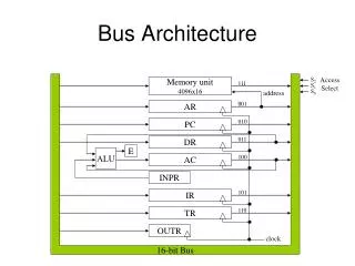
This document explores the intricacies of bus architecture in computer systems, emphasizing the 4096x16 memory unit, instruction formats, and the vital role of the Control Unit. It covers the fetching, decoding, and executing of instructions, particularly focusing on I/O operations and interrupt mechanisms. Key topics include direct and indirect memory addressing, the interrupt cycle, and how interrupts can be managed to optimize I/O processes. The text is structured around the principles of architecture as taught in CSC321, providing practical insight and examples pertaining to instruction handling.

E N D
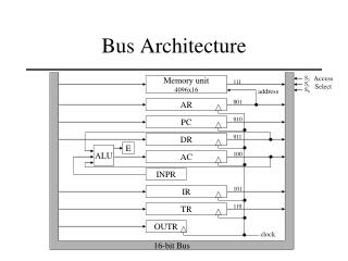
Bus Architecture S2 Access Select Memory unit 4096x16 111 S1 S0 address 001 AR 010 PC 011 16-bit Bus DR E ALU 100 AC INPR 101 IR 110 TR OUTR clock CSC321
Instruction Format 15 14 12 11 0 I opcode address I = 0 means direct memory address I = 1 means indirect memory address CSC321
The Control Unit Instruction Register (IR) 15 14 - 12 11 - 0 Other Inputs 3x8 Decoder 12 Control Unit D7 – D0 n I T15 – T0 4x16 Decoder Increment Sequence Counter Clear Master Clock CSC321
Decoding the Instruction • We’ve seen how to fetch and decode instructions in RTL notation • We now need to look at how to execute each instruction T0 T1 T2 = 1, register or I/O = 0, memory reference = 1, I/O = 0, register = 1, indirect = 0, direct T3 T3 T3 T3 CSC321
Input/Output Instructions • Recall the I/O instructions posed a potential problem • Their purpose is to set up loop structures waiting for an input/output device to become available • This could cause large amounts of valuable time to be wasted CSC321
Interrupts • To alleviate this problem we introduce interrupts into the system • Two instructions enable and disable interrupts • Sometimes we don’t want to be interrupted such as when we’re doing something important or we’re already servicing and interrupt • ION (enable interrupts) D7IT3B7: IEN ← 1, SC ← 0 • IOF (disable interrupts) D7IT3B6: IEN ← 0, SC ← 0 • We also introduce another flip-flop, R, which tells the system when there is an interrupt to be handled CSC321
Interrupt Cycle • Interrupts are subroutine calls with a couple of differences • They come at arbitrary times during program execution • The start address of the interrupt service routine (subroutine) is a predetermined, fixed location in memory CSC321
Set up the interrupt service routine I/O device is ready so signal an interrupt Once set-up, the system carries on as usual Interrupt Cycle The interrupt service routine ends with a BUN to indirect address 0 = 0 = 1 = 0 = 1 = 1 = 0 = 1 = 0 CSC321
Interrupt cycle sets return address here and PC here PC is here when the interrupt occurred 0x00 0x00 0x11 0x01 0x01 0 BUN 0x51 0 BUN 0x51 0x10 0x10 0x11 0x11 0x51 0x51 INTERRUPT SERVICE ROUTINE INTERRUPT SERVICE ROUTINE 1 BUN 0x00 1 BUN 0x00 Interrupt Cycle CSC321
Interrupt Cycle Implementation • To implement the interrupt cycle we introduce the R flip-flop\ • To utilize it we modify our fetch/decode RTL as follows CSC321
Modified Fetch/Decode • It was this… • We modify it to this… T0: AR ← PC T1: IR ← M[AR], PC ← PC + 1 T2: D0, … D7 ← Decode IR(12-14), AR ← IR(0-11), I ← IR(15) R’T0: AR ← PC R’T1: IR ← M[AR], PC ← PC + 1 R’T2: D0, … D7 ← Decode IR(12-14), AR ← IR(0-11), I ← IR(15) CSC321
Modified Fetch/Decode • We must also add the interrupt cycle handler RTL… RT0: AR ← 0, TR ← PC RT1: M[AR] ← TR, PC ← 0 RT2: PC ← PC + 1, IEN ← 0, R ← 0, SC ← 0 CSC321
Remainder of Chapter 5 • The remainder of the chapter discusses how to convert the Control Unit RTL into logic gates • This is really nothing more than defining AND/OR/NOT/XOR gates to handle the conditions on the RTL statements • Thus, I’m not going to spend any time on it and won’t hold you accountable for it but… • You should read it over once to get a feel for how all this stuff ties together CSC321
Homework • Problems 5-9, 5-10, 5-11, 5-12 • Due next lecture CSC321
Initial Memory Contents 47 47 PC 5135 0C00 IR 48 3160 3160 AR DR A0A0 1355 DA00 AC 01FF 1365 2150 1 I 1375 C135 1505 FFFF CSC321