Universal Serial Bus System Architecture (1)
280 likes | 573 Vues
Universal Serial Bus System Architecture (1). overview. The big picture – overview. USB Bus Topology. USB Host There is only one host in any USB system. The USB interface to the host computer system is referred to as the Host Controller.

Universal Serial Bus System Architecture (1)
E N D
Presentation Transcript
USB Host • There is only one host in any USB system. • The USB interface to the host computer system is referred to as the Host Controller. • A root hub is integrated within the host system to provide one or more attachment points. • USB Devices • USB devices are one of the following: • Hubs, which provide additional attachment points to the USB • Functions, which provide capabilities to the system, such as an ISDN connection, a digital joystick, or speakers.
USB bus protocol • The USB is a polled bus. • The Host Controller initiates all data transfers. • All bus transactions involve the transmission of up to three packets. • Token packet • Each transaction begins when the Host Controller, on a scheduled basis, sends a USB token packet describing the type and direction of transaction, the USB device address, and endpoint number. • Data packet • The USB device that is addressed selects itself by decoding the appropriate address fields. In a given transaction, data is transferred either from the host to a device or from a device to the host. The direction of data transfer is specified in the token packet. The source of the transaction then sends a data packet or indicates it has no data to transfer. • Handshake packet • The destination, in general, responds with a handshake packet indicating whether the transfer was successful.
USB pipe • The USB data transfer model between a source or destination on the host and an endpoint on a device is referred to as a pipe. • stream pipe • Message pipe • Pipes have associations of data bandwidth, transfer service type, and endpoint characteristics like directionality and buffer sizes. Most pipes come into existence when a USB device is configured. • One message pipe, the Default Control Pipe, always exists once a device is powered, in order to provide access to the device’s configuration, status, and control information. • The transaction schedule allows flow control for some stream pipes. At the hardware level, this prevents buffers from underrun or overrun situations by using a NAK handshake to throttle the data rate. When NAKed, a transaction is retried when bus time is available.
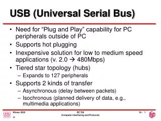
Plug and play • 當pc一接上電源時, 所有利用usb所連接的裝置與集線器都預設為位址0 • 接著pc就向usb查詢, 若發現第一個device其位址為0, 則assign 一個新位址給他, 然後再向下尋找第二個位址為0的裝置或集線器 • 最多可連接127個devices • 在配給新位址的同時, pc亦為每個device或hub載入其驅動程式 • 若有一新的裝置被接上時, 其預設為位址0, pc就會確認並載入其相對應的驅動程式, 並分配一個尚未使用的位址給它 • 一旦某個device突然被拔取後, pc可經由D+或D-的電壓變化測到裝置被移除掉, 就將其位址收回並列入可使用的位址名單中. • 每個device (function)有4-bit endpoint address (為register或memory位址) , 可當輸入或輸出 port • 所以在一個單獨的小管線(pipe)內最多可再分割成16組的微管線(micro-pipe), 也就是可對16個輸出/入的端點(共32個端點endpoint)定址 • 位址0 的in, out是給開機時之初始控制傳輸用, 真正可用的endpoint number為15, 即30個endpoint
Data flow types • The USB architecture comprehends four basic types of data transfers: • Control Transfers • Used to configure a device at attach time and can be used for other device-specific purposes, including control of other pipes on the device. • Bulk Data Transfers (ex: printer or scanner) • 用於傳輸大量資料,這種資料是非週期性或是無傳輸速度限制,例如:USB印表機,較不即時的資料傳輸並不會導致列印工作資料的流失或損毀. • Interrupt Data Transfers (polling, ex: mouse or keyboard) • 用於傳統個人電腦中被認為是靠中斷驅動的裝置。因為USB不支援硬體中斷,那些必須靠中斷驅動的USB裝置必須被週期性的POLLING,以得知是否有資料需要傳送。例如:在傳統個人電腦系統中,每當鍵盤上有一個鍵被壓下,鍵盤會發出一個硬體中斷以通知處理器去執行一段軟體斷程序,以便服務鍵盤。如果是USB鍵盤,它將週期性的被詣問以便決定有是否有資料要傳送。詢問的週期當然是很重要(它的頻率必須足夠以免資料移失,但也不能太高以免佔用太多匯流排頻寬。 • Isochronous Data Transfers • 需要固定之傳送速率應用, 使用這種傳應用必須確保發送端與接收端的速率是相互吻合的。例如:USB麥克風與喇叭即是用此種傳輸。
USB bus interface layer • provides physical/signaling/packet connectivity between the host and a device. • USB Device Layer • is the view the USB System Software has forperforming generic USB operations with a device. • Function Layer • provides additional capabilities to the host via an appropriate matched client software layer.
USB Host • The host’s logical composition is • USB Host Controller • Aggregate USB System Software (USB Driver, Host Controller Driver, and host software) • Client.
USB Devices • A USB physical device’s logical composition is • USB bus interface • USB logical device • Function.
Physical Bus Topology • USB attachment points are provided by a special class of USB device known as a hub. • The additional attachment points provided by a hub are called ports. • A host includes an embedded hub called the root hub. • USB devices that provide additional functionality to the host are known as functions. • When multiple functions are combined with a hub in a single package, they are referred to as a compound device.
USB Communication Model • 與一般其它匯流排上的裝置不同, USB並不宜接消耗系統資源 • USB裝置並不被對映到記憶體或I/O位址空間, 也不會佔用IRQ或DMA channel • 所用transaction皆由host啟動
Transfer Management • Client Software: • Consumes/generates function-specific data to/from a function endpoint via calls and callbacks requesting IRPs with the USBD interface. • A software client normally requests data transfers via I/O Request Packets (IRPs) to a pipe and then either waits or is notified when they are completed. • USB Driver (USBD): • Converts data in client IRPs to/from device endpoint via calls/callbacks with the appropriate HCD. A single client IRP may involve one or more transfers. • Host Controller Driver (HCD): • Converts IRPs to/from transactions (as required by a Host Controller implementation) and organizes them for manipulation by the Host Controller. • Interactions between the HCD and its hardware is implementation-dependent and is outside the scope of the USB Specification. • Host Controller: • Takes transactions and generates bus activity via packets to move function-specific data across the bus for each transaction.
Transaction Tracking • 當一個client driver希望對某個endpoint of device做傳輸(transfer)時, 它利用IO Request Packet (IRP)去呼叫USB Driver, 以啟動transfer • 一個transfer可能需要傳輸大量資料,因為USB是shared bus, 所以將傳輸分成多個transaction來完成 • 一個transaction乃是由多個packet組成(看是那種傳輸, 其transaction的packet組成方式不太一樣 • USB的傳輸基礎是以1ms為一個frame來排程