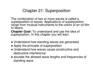
Superposition
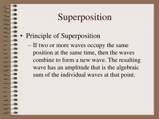
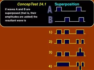
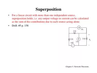
Superposition. For a linear circuit with more than one independent source, superposition holds, i.e. any output voltage or current can be calculated as the sum of the contributions due to each source acting alone. Drill: #5 p. 158. 3A. 2 W. +. 2 W. 2 W. V o. 1A. 14V. +. Linear

Superposition
E N D
Presentation Transcript
Superposition • For a linear circuit with more than one independent source, superposition holds, i.e. any output voltage or current can be calculated as the sum of the contributions due to each source acting alone. • Drill: #5 p. 158 3A 2 W + 2 W 2 W Vo 1A 14V +
Linear Resistive Elements vo + va ib + Proportionality • For a linear circuit when any independent sources is acting alone, any output voltage or current is proportional to that single source i.e. if the source is multiplied by K, the output is also multiplied by K. • Drill: #2(a) p. 157: vo= 3v12+4v22 • Drill: #9 p.158: • va=10V and ib=0 vo=5V • va=0 and ib=10A vo=1V • va=20V and ib=20A vo=?
+ + Vo R2 Superposition and Dependent Sources • Method 1: Apply superposition to independent sources ONLY. • Method 2: Apply superposition to dependent and independent sources • Drill: #21 p. 160: • Treat the dependent current source as an independent source Ix • Find the output Vo and the control Vg by superposition: • Ix = 0 Vo1= Vg1 = • Vi = 0 Vo2= Vg2 = • (1) Vo=Vo1+Vo2 (2) Vg = Vg1+Vg2 Solve (2) for Vg and plug into (1) gmVg + Vg R1 Vin
+ i R i i + + + v v v + R R Vs Is Is Dependent sources 18V 2 W 3 W 5 W 2 W Vs = IsR Vs = IsR + + 1A 12V Source Transformation Theorem • A series connection of a voltage source, Vs, and a resistor, R, is equivalent to a parallel connection of a current source, Is=Vs/R, and a resistor R. (Equivalent have the same i-v relationship) • Drill: #22 p160: Apply source transformation theorem to find P(5W) Since P= RI2 = V2/R then need I(5W) or V(5W) R i + v Vs Independent sources
+ i i Passive Network Rth + + Vth v v Thévenin Theorem for Passive Networks • Passive network: circuit containing resistors and independent sources. • Thévenin theorem for passive networks: Any two-terminal passive network can be reduced to an equivalent two-terminal network consisting of a voltage source, Vth, in series with a resistance, Rth.
i i Passive Network + + Rth IN v v Norton Theorem for Passive Networks • Norton theorem for passive networks: Any two-terminal passive network can be reduced to an equivalent two-terminal network consisting of a current source, IN, in parallel with a resistance, Rth.
Finding the Thevenin /Norton Equivalent • Method 1: use source transformation to reduced the circuit to a resistance in series/parallel with voltage/current source • Drill: #27 p.160 • Method 2: calculate Voc , and find Rth=Req with all independent sources set to zero i.e. Vs= 0 and Is= 0. • Drill: #28 p.161 • Method 3: calculate Voc and isc Vth=Voc , IN=isc and Rth= Rth = Voc/isc • Drill: #29 p. 161
+ + + v Vth i isc Finding Thevenin /Norton Equivalent (cont.) • Method 4: i-v measurements • Drill: #37 p.162 i i Rth + + Vth v Rth IN v
Thévenin&Norton Theorems for Active Networks • Linear active network: linear circuit containing resistors, independent and dependent sources. • Thévenin theorem for linear active networks: almost any two-terminal linear active network can be reduced to a Thévenin equivalent. • Norton theorem for active networks:almost any two-terminal linear active network can be reduced to a Norton equivalent. • ONLY method 3 and 4can be used to find the Thévenin/Norton equivalent of a linear active network. • Drill: #31 p. 162 • Drill: #35 p.162
+ + Rs RL Vs PL Rs RL Maximum Power Transfer • Practical voltage/current sources dissipate part of the power they deliver internally (they heat up). • Internal power dissipation modeled by a resistor: • Power delivered to a load, RL/ power dissipated by RL: Rs + Rs Vs Is Vs Is Ideal Sources Practical Sources
6 W + 3 W RL VL 3A Maximum Power Transfer (Cont.) • Maximum power transfer for RL = Rs • Drill: #45 p. 164