FIGURE 6–4 A red brake warning lamp.
240 likes | 723 Vues
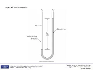
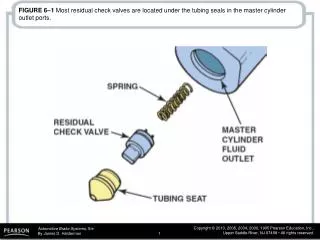
FIGURE 6–1 Most residual check valves are located under the tubing seals in the master cylinder outlet ports. FIGURE 6–2 The momentary drop in pressure created when the brakes are released can draw air into the hydraulic system.

FIGURE 6–4 A red brake warning lamp.
E N D
Presentation Transcript
FIGURE 6–1 Most residual check valves are located under the tubing seals in the master cylinder outlet ports.
FIGURE 6–2 The momentary drop in pressure created when the brakes are released can draw air into the hydraulic system.
FIGURE 6–3 The use of cup expanders is the main reason why residual check valves are not used in most braking systems today.
FIGURE 6–5 A leak in the hydraulic system causes unequal pressures between the two different brake circuits. This difference in pressures causes the plunger inside the pressure-differential switch to move, which completes the electrical circuit for the red brake warning lamp.
FIGURE 6–6 The pressure-differential switch piston is used to provide the electrical ground for the red brake warning light circuit.
FIGURE 6–9 Many proportioning valves are mounted directly to the master cylinder in the outlet to the rear brakes.
FIGURE 6–10 Typical proportioning valve pressure relationship. Note that, at low pressures, the pressure is the same to the rear brakes as is applied to the front brakes. After the split point, only a percentage (called the slope) of the master cylinder pressure is applied to the rear brakes.
FIGURE 6–11 A Chrysler proportioning valve. Note that slope and split point are stamped on the housing.
FIGURE 6–12 These two proportioning valves are found under the vehicle on this Dodge minivan.
FIGURE 6–13 The proportioning valve piston can travel within the range shown without reducing pressure to the rear brakes.
FIGURE 6–14 At the split point, the proportioning valve piston closes the fluid passage through the valve.
FIGURE 6–15 A height-sensing proportioning valve provides the vehicle with variable brake balance. The valve allows higher pressure to be applied to the rear brakes when the vehicle is heavily loaded and less pressure when the vehicle is lightly loaded.
FIGURE 6–16 A stepped cam is used to alter the split point of this height-sensing proportioning valve.
FIGURE 6–17 A proportioning valve pressure test can be performed using two pressure gauges—one to register the pressure from the master cylinder and the other gauge to read the pressure being applied to the rear brakes. This test has to be repeated in order to read the pressure to each rear wheel.
FIGURE 6–18 A metering valve when the brakes are not applied. Notice the brake fluid can flow through the metering valve to compensate for brake fluid expansion and contraction that occurs with changes in temperature.
FIGURE 6–19 A metering valve under light brake pedal application.
FIGURE 6–20 A metering valve during a normal brake application.
FIGURE 6–22 Combination valve containing metering, pressure-differential (warning switch), and proportioning valves all in one unit. This style is often called a “pistol grip” design because the proportioning valve section resembles the grip section of a handgun.