1 / 58

Figure 9.1 U-tube manometer.

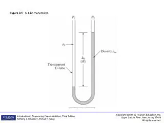
Figure 9.1 U-tube manometer. Figure 9.2 Well-type manometer. Figure 9.3 Inclined manometer. Figure 9.4 Mercury barometer. Figure 9.5 Bourdon gage. Figure 9.6 Dead-weight tester. Figure 9.7 Strain-gage pressure transducer. Figure 9.8 LVDT pressure transducer.

salene
Télécharger la présentation

Figure 9.1 U-tube manometer.

An Image/Link below is provided (as is) to download presentation Download Policy: Content on the Website is provided to you AS IS for your information and personal use and may not be sold / licensed / shared on other websites without getting consent from its author. Content is provided to you AS IS for your information and personal use only. Download presentation by click this link. While downloading, if for some reason you are not able to download a presentation, the publisher may have deleted the file from their server. During download, if you can't get a presentation, the file might be deleted by the publisher.

E N D

Presentation Transcript


  1. Figure 9.1 U-tube manometer.

  2. Figure 9.2 Well-type manometer.

  3. Figure 9.3 Inclined manometer.

  4. Figure 9.4 Mercury barometer.

  5. Figure 9.5 Bourdon gage.

  6. Figure 9.6 Dead-weight tester.

  7. Figure 9.7 Strain-gage pressure transducer.

  8. Figure 9.8 LVDT pressure transducer.

  9. Figure 9.9 Capacitive pressure transducer.

  10. Figure 9.10 Piezoelectric pressure transducer.

  11. Figure 9.11 McLeod vacuum gage. (Based on Van Atta, 1965.)

  12. Figure 9.12 Pirani thermal-conductivity vacuum gage: (a) sensing chamber; (b) bridge circuit.

  13. Figure 9.13 Ionization vacuum-gage circuit. (Based on Van Atta, 1965.)

  14. Figure 9.14 Thermocouple.

  15. Figure 9.15 Thermocouple with reference junction.

  16. Figure 9.16 Output of some common thermocouples.

  17. Table 9.2 (continued) Millivolt Output of Common Thermocouples (Reference Junction at 0°C)

  18. Table 9.2 (continued) Millivolt Output of Common Thermocouples (Reference Junction at 0°C)

  19. Figure 9.17 Common sheathed thermocouple probe.

  20. Figure 9.18 Four series thermocouples forming a thermopile.

  21. Figure 9.19 Thermocouple connections with data-acquisition systems.

  22. Figure E9.6a,b

  23. Figure 9.20 Resistance temperature detectors: (a) platinum wire; (b) thin film.

  24. Figure 9.21 Wheatstone bridge circuits for RTD: (a) two-wire; (b) three-wire.

  25. Figure 9.22 Four-wire RTD circuits.

  26. Figure 9.23 Thermistor circuit.

  27. Figure 9.24 Linearization circuit for thermistor.

  28. Figure 9.25 Liquid-in-glass thermometer.

  29. Figure 9.26 Bimetallic strip devices. [(b) and (c) Based on Doebelin, 1990.]

  30. Figure 9.27 Pressure thermometer.

  31. Figure 9.28 Blackbody monochromatic emissive power.

  32. Figure 9.29 (a) Disappearing-filament optical pyrometer; (b) appearance to observer.

  33. Figure 9.30 Schematic of a radiation thermometer.

  34. Figure 9.31 Field of view for radiation thermometer.

  35. Figure 9.32 Surface-temperature measurement.

  36. Figure 9.33 Long circular fin.

  37. Figure 9.34 Conduction error source in gas temperature measurement.

  38. Figure E9.8

  39. Figure 9.35 Radiation error source.

  40. Figure 9.36 Reducing radiation error using a radiation shield.

  41. Figure 9.37 Sling psychrometer.

  42. Figure 9.38 Psychrometric chart.

  43. Figure 9.39 Refraction and reflection of light rays at a dielectric interface defined by refractive indices n1 and n2 (n1 > n2 )

  44. Figure 9.40 Typical optical fiber.

  45. Figure 9.41 Ray transmission through an optical fiber.

  46. Figure 9.42 Two types of fiber-optic sensors: (a) extrinsic; (b) intrinsic.

  47. Figure 9.43 Reflective fiber-optic response curve for displacement measurement. (After Krohn, 2000.)

More Related