Download
1 / 149
1.49k likes | 1.7k Vues
Fermi Edge Polaritons Formed By Electron-hole Pairs Interacting With Cavity-confined Photons. Yossi Michaeli Supervisor: Prof. Elisha Cohen M.Sc. Seminar September, 2010. Outline. Introduction Electronic properties of quantum wells Optical properties of quantum wells

E N D
Fermi Edge Polaritons Formed By Electron-hole Pairs Interacting With Cavity-confined Photons Yossi Michaeli Supervisor: Prof. Elisha Cohen M.Sc. Seminar September, 2010
Outline • Introduction • Electronic properties of quantum wells • Optical properties of quantum wells • Optical susceptibility modeling • Bare quantum well optical characterization for • Undoped structure • Doped structures with various 2DEG concentrations • Semiconductor Microcavities • Bare microcavity optical modeling • Optical characterization of Quantum wells embedded in microcavities for • Undopedstructure • Doped structures with various 2DEG concentrations • Conclusions • Acknowledgments
Two-Level Absorber Multi photon modes (free space) Single confined photon mode (cavity) Reversible interaction Non-perturbative Strong coupling Mixed absorber-field modes (Rabi splitting) • Irreversible interaction • Spontaneous emission • Weak coupling
Structure Schrodinger-Poisson Computation Outline QW band edge profiles Schrodinger Equation Solver – the 2DEG concentration – the phenomenological broadening factor T – ambient temperature Conduction and valence subbands at Active Region SubbandsDispersion Momentum matrix elements Material Parameters Optical Susceptibility Hartree-Fock Model Free Carrier Model TE and TM optical susceptibility MC Reflection Entire Structure Full structure reflection for various detunings Coupled Oscillator Model Fit
Schrodinger-Poisson Overview Schrodinger Equation Solver SubbandsDispersion Optical Susceptibility Hartree-Fock Model Free Carrier Model MC Reflection Coupled Oscillator Model Fit
Conduction Subbands • Bands are assumed to be parabolic and the problem reduces to a one-dimensional Schrödinger equation of the form • The conduction band wave function • are the conduction band wave functions for the bulk case.
Undoped QW Example Calculated using the effective mass model for an undoped200 Å quantum well at T=2K Subbands dispersion The ratio between the total density of states of the conduction subbandsand the first conduction subband
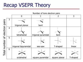
Valence Subbands – k.p Approach • Single- and two-band k.p • Coupling to other bands accounted perturbatively. • Predicts an analytical effective mass tensor (heavier/lighter than ). • Kane’s Model • 8 bands (CB+3 VB with spin) treated exactly. • Coupling with the other bands neglected. • HH band comes out with wrong sign and value. • No warping predicted (i.e., isotropic) for finite . • Luttinger-Kohn Model (for degenerate bands with spin-orbit) • 6 VBs treated exactly; can be extended to include CBs as well. • Other bands are included via Löwdin’s technique. • Warping of the VBs is predicted. • Pikus-BirModel • Just like LK Hamiltonian, but includes the effects of strain.
Valence Subbands - Luttinger-Kohn Model • The 4X4 LK k.p model Hamiltonian
Valence Subbands(cont’) • Broido and Sham’s approach block diagonalizes the Hamiltonian into two 2X2 blocks • Taking into account the potential profile of the well, the effective mass equation is • are the envelope functions corresponding to the transformed Bloch functions.
Valence Subbands (cont’) • For heterostructures, because of the material composition modulation, the valence band edge energies become position dependent. • Also the potentials and Luttingerparameters and become position dependent. • remain position independent, but in the growth direction . • Hamiltonian hermiticity is preserved only if
Valence Subbands(cont’) • The Hamiltonian components become (with ) • The wavefunction can be written as
Valence Subbands (cont’) • The following quantities are matched across the material interfaces of the well for the Hamiltonian hermiticity • The effective mass equation can be solved generally using the transfer matrix method.
Undoped QW Valence Subbands Calculated using the 2-Band k.p model for an undoped200 Å quantum well at T=2K Subbands dispersion calculated for [100] and the [110] crystal directions The ratio between the total density of states of the valence subbands and the first conduction subband
Undoped QW Electron Wavefunctions Wavefunctions calculated at the Brillouin zone center () for an undoped200 Å quantum well at T=2K Conduction subbands Valence heavy-hole (HH) subbands Valence light-hole (LH) subbands
Undoped QW Electron Wavefunctions Wavefunctionscalculated away from the Brillouinzone center () for an undoped 200 Å quantum well at T=2K. The dotted lines represent the Brillouin zone center functions. Heavy-holes Light-holes
Influence of Doping • Introduction of additional carriers via various forms of doping may add significant additional potential atop of the band-edge potential. • The electrostatics of the system must be solved in combination with the quantum mechanical problem – self-consistent Schrödinger-Poisson model. • Poisson’s equation for the additional electrostatic potential
2D Electron Gas (2DEG) -Doping Photoexcitation (Schubert, 1996)
2DEG (cont’) • In the low temperature regime, and assuming that all available states are occupied in the first conduction subband, the Fermi energy of is • The wavevector of the top most occupied state is
(a) -Doping 200 Å quantum well with symmetrical -doping layers, introduced 1000 Å from the well barriers, inducing a 2DEG with a concentration of in the active region Volume charge density Conduction band-edge profile before and after the self-consistent calculation Valence band-edge profiles (b) (c)
-Doped QW Band Edges Calculated conduction and valence band edges of a quantum well with a variable 2DEG concentration introduced by symmetric -doped cladding layers.
-Doped QW Electron Wavefunctions Wave functions calculated at the Brillouin zone center () for a -doped 200 Å quantum well at T=2K with a 2DEG concentatrion of Conduction subbands Valence heavy-hole (HH) subbands Valence light-hole (LH) subbands
-Doped QW Subbands Calculated for a -doped 200 Å quantum well at T=2K, with 2DEG concentrations of , and . First conduction subband First four valence subbands
Dipole Matrix Element • For the presented two-level model of the subbands the transition matrix elements are given • TE – • TM -
Undoped QW Dipole Matrix Elements Calculated at the Brillouin zone center () for an udoped200 Å quantum well at T=2K, where first two conduction and four valence subbandsare considered TE polarization TM polarization
Doped QW Dipole Matrix Elements Calculated at the Brillouin zone center () for a doped 200 Å quantum well at T=2K, with various 2DEG concentrations in the range of to TE polarization TM polarization
Schrodinger-Poisson Overview Schrodinger Equation Solver SubbandsDispersion Optical Susceptibility Hartree-Fock Model Free Carrier Model MC Reflection Coupled Oscillator Model Fit
Many-Body Problem • We can split the regular Schrodinger equation in two separate, independent eigenvalue problems, one for the cores and another for the electrons. • Consider the electron-Hamiltonian • We can determine an eigenvalue problem for each configuration
Many-Body Problem (cont’) • In the adiabatic approximation the Hamiltonian becomes • In the special case where there is no interaction between the particles • For a -particle system, we can define a basis in the Hilbert space as the product of single-particle eigenstates
Second Quantization • Now we can combine the many-body formulation with the Fockrepresentation. • First of all, we consider the non-interacting part of the many-body Hamiltonian, • The matrix element becomes
Second Quantization (cont’) • In the creation and annihilation notation we can write where and are, respectively, the annihilation and creation operators for an electron in state and band . • The non-interacting part of the Hamiltonian becomes • Following the same procedure, the interacting part can be computed to be • The matrix element is
Second Quantization (cont’) • We add the Hamiltonian the interaction between the material and the electrical field. • After evaluating the two matrix elements the Hamiltonian can be written as where
Second Quantization (cont’) • For a simpler notation we can define the following two operators: and are, respectively, the hole creation and annihilation operators. • Using these two operators the Hamiltonian can be written as
Second Quantization (cont’) • The first term describes the energies (Note that the energy term is now positive and so is the effective mass • The second term incorporates the Coulomb effects: • The first two terms are the intraband carrier interactions • The last one the interaction between the valence band holes and conduction band electrons. • The third term describes the carrier-field interaction, where is the radiation field and is the dipole matrix element.
Equations of Motion • Our aim now is to evaluate the microscopic polarization, . • This can be achieved by solving the Heisenberg equation of motion, which can be defined for a general operator • The equation of is coupled with two other equations that represent the electron () and hole () distributions. • The equations of motion must be solved for every combination of conduction and valence subbands.
Equations of Motion (cont’) • These three equations in their most general form
Equations of Motion (cont’) • The transition energy is given by • As we can see, the Coulomb interaction in the Hamiltonian couples the two-operator expectation values with four-operator expectation values, yielding an infinite set of equations. • To solve the equations we must resort to approximations: • Free carrier • Hartree-Fock • Second order collisions
Classical Gain Medium • By rearranging Maxwell’s equations we obtain the wave equation for the electrical field of the form • We assume the following where .
Classical Gain Medium (cont’) • Assuming slowly varying envelope approximation, and separating real and imaginary parts leads to with . • Defining amplitude gain as , the intensity gain is • The polarization amplitude and complex susceptibility must be found quantum-mechanically.
Gain Equation • We want to find the dependence of the intensity gain on the microscopic polarization . To this end we can state that • The complex susceptibility is • The intensity gain is thus
Free Carrier Approximation • The simplest approximation is to neglect the interacting parts of the Hamiltonian, i.e. the charge carriers are free, moving without interacting with the other particles in system, and no scattering or collisions occur. • This corresponds to setting in the equations of motion for , and . • The simplified set of equations is now
Free Carrier Approximation (cont’) • Model assumptions: • The distributions the electrons and holes become Fermi-Dirac functions, i.e. the conduction and valence bands are considered to be two carrier reservoirs. • The carrier-carrier scattering drives the system towards this quasi equilibrium, i.e. and . The distributions remain constant, but there are electrons or holes that scatter in a way that scattering into each state is exactly balanced by the scattering out of that state. • This process induces a decay of which can be modeled by a dephasing rate . • The equation to be solved reduces to
Free Carrier Approximation (cont’) • It is convenient to work with a slowly-varying microscopic polarization amplitude • The eq. of motion can now be written as • We also make a radial approximation for , assuming there is no angular dependence. Furthermore, we need the stationary solutions for the polarization, i.e.
Free Carrier Approximation (cont’) • We must add a summation over all possible transitions for the polarization and summation over the dipole matrix element and its complex conjugate
Screened Hartree-Fock Approximation • Now we incorporate the Coulomb potential, which is attractive between electrons and holes and repulsive for particles in the same band. • In the equations of motion we observe that expectation values of products of two-particle operators are coupled to those of products of four-particle operators, which, in turn, are coupled to six-operator expectation values, and so on.
Screened HF Approximation (cont’) • The HF approximation truncates the hierarchy by studying the many-electron atom- higher-order expectation values are factorized into all possible products of the second-order averages • The Hartree-Fock limit of the equation of motion yields important many-body effects, such asband gap renormalization and interband Coulomb enhancement.
Screened HF Approximation (cont’) • This approach for a two-operator expectation value • For four operator one • And so on. The result is a hierarchy of equations, where each succeeding equation describes a correlation contribution that is of higher order than the one before.
Screened HF Approximation (cont’) • As an example for this factorization we can write • We can assume that and and thus . • This can be further simplified by the Random Phase Approximation(RPA): the expectation value is set to 0 when both operators are in phase, i.e.. • By applying this procedure we obtain