Download
1 / 39

E N D
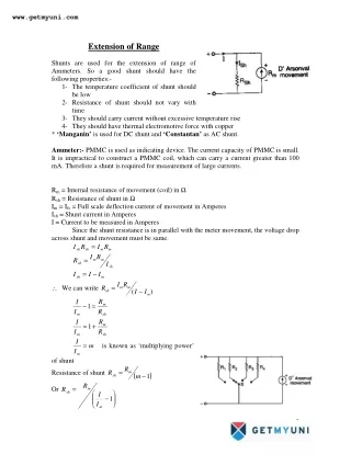
www.getmyuni.com Extension of Range Shunts are used for the extension of range of Ammeters. So a good shunt should have the following properties:- 1-The temperature coefficient of shunt should be low 2-Resistance of shunt should not vary with time 3-They should carry current without excessive temperature rise 4-They should have thermal electromotive force with copper * ‘Manganin’ is used for DC shunt and ‘Constantan’ as AC shunt. Ammeter:- PMMC is used as indicating device. The current capacity of PMMC is small. It is impractical to construct a PMMC coil, which can carry a current greater than 100 mA. Therefore a shunt is required for measurement of large currents. Rm = Internal resistance of movement (coil) in Ω Rsh = Resistance of shunt in Ω Im = Ifs = Full scale deflection current of movement in Amperes Ish = Shunt current in Amperes I = Current to be measured in Amperes Since the shunt resistance is in parallel with the meter movement, the voltage drop across shunt and movement must be same. m m sh sh R I R I = R I R = m m I sh sh = − I I I sh m I R ∴ We can write = R m m − ( ) I I sh m R I m −1 = I R m I sh R m =1 + I R m I sh = is known as ‘multiplying power’ m I m of shunt R = Resistance of shunt R m ( ) 1 − m sh R = Or R m sh I − 1 I m 1
www.getmyuni.com Multi Range Ammeter:- Let m1, m2, m3, m4 be the shunt multiplying powers for current I1, I2, I3, I4. R R m sh = ( ) 1 − m 1 1 R = R m ( ) 1 − m 2 sh 2 R = R m ( ) 1 − m 3 sh 3 R = R m ( ) 1 − m 4 sh 4 Voltmeter:- extension of range. Im = Deflection current of movement Rm = Internal resistance of movement Rs = Multiplier resistance V = Full range voltage of instrument ( m s m R R I V + = R I V R = For measurement of voltage a series resistor or a multiplier is required for ) − V m m = − R s m I I m m * For more than 500 V multiplier is mounted outside the case. Multi Range Voltmeter: V R − = 1 1 R s m I m V 2 = − R R 2 s m I m V 3 = − R R 3 s m I m V 4 = − R R 4 s m I m * For average value divide the reading by 1.11. For peak value multiply the voltage by 1.414. To get peak-to-peak ratio multiply the reading by 2.828. ** Thermocouple and hot wire instruments are used for measurement of true power and rms value of voltage & current. Voltmeter & Ammeter by Moving Coil Instrument:- Same process as applied in PMMC. 2
www.getmyuni.com Electrodynamic type Voltmeter & Ammeter:- Shunt is connected across the circuit for ammeter and multiplier resistance is connected in series for voltmeter. Numerical Extension of Range Example 1:- A moving coil ammeter has a full scale deflection of 50 µ µ µ µ Amp and a coil resistance of 1000 Ω Ω Ω Ω. What will be the value of the shunt resistance required for the instrument to be converted to read a full scale reading of 1 Amp. Solution 1:- Full scale deflection current Im = Instrument resistance Ω =1000 m R Total current to be measured A I 1 = − 6 50 * 10 A 1000 R m = = Resistance of ammeter shunt required R sh 1 I − 6− 1 1 − 50 * 10 I m Example 2:- The full scale deflection current of an ammeter is 1 mA and its internal resistance is 100 Ω Ω Ω Ω. If this meter is to have scale deflection at 5 A, what is the value of shunt resistance to be used. Solution 2:- Full scale deflection current Im = Instrument resistance =100 m R Total current to be measured A I 5 = = 1 . 0 001 mA A Ω . 100 R m = = Resistance of ammeter shunt required R sh 5 I − − 1 1 . 0 01 I m = Ω Example 3:- The full scale deflection current of a meter is 1 mA and its internal resistance is 100 Ω Ω Ω Ω. If this meter is to have full-scale deflection when 100 V is measured. What should be the value of series resistance? Solution 3:- Instrument resistance =100 m R = = = V R . 0 020004 R sh Ω − 3 Full-scale deflection current 1 1 * 10 Im V mA A Voltage to be measured 100 V 100 = − = − = Ω Required series resistance 100 99 900 , R se m − 3 I 1 * 10 m 3
www.getmyuni.com Example 4:- A PMMC instrument gives full scale reading of 25 mA when a potential difference across its terminals is 75 mV. Show how it can be used (a) as an ammeter for the range of 0-100 A (b) as a voltmeter for the range of 0-750 V. Also find the multiplying factor of shunt and voltage amplification. Solution 4:- across drop Potential Rm − 3 min ter als 75 * 10 = = = Ω Instrument resistance 3 − 3 Instrument current 25 * 10 (a)Current to be measured = I 100 I A 100 = = 3= Multiplying power of shunt 4000 m − m I 25 * 10 Shunt resistance required for full scale deflection at 100 A R R sh 1 4000 1 (b) Voltage to be measured V 750 m m I 750 = 3 3 − 4 m = = = = = Ω . 7 50 * 10 . 0 75 m − − 3999 750 m = V V = − = − = Ω 3 29 997 , R R se − 3 25 * 10 3= Voltage amplification 10000 Ans. − 75 * 10 Example 5:- A moving coil instrument gives full scale deflection of 10 mA and potential difference across its terminals is 100 mV. Calculate (a) shunt resistance for full-scale deflection corresponding to 200 A (b) Series resistance for full reading corresponding to 1000 V. Solution 5:- across drop Potential Rm − 3 min ter als 100 * 10 = = = Ω Instrument resistance 10 − 3 Instrument current 10 * 10 (a) Shunt resistance required for full scale deflection corresponding to 200 A R R 10 − 4 m = = = Ω . 5 00025 * 10 sh 200 I − − 1 1 − 3 10 * 10 I m (b)Series resistance required for full scale deflection corresponding to 1000 V 1000 m m I V = − = − = Ω 10 99 990 , R R se − 3 10 * 10 Example 6:- A moving coil instrument having internal resistance of 50 Ω Ω Ω Ω indicates full scale deflection with a current of 10 mA. How can it be made to work as (i) a voltmeter to read 100 V on full scale (ii) an ammeter of 1 A, on full scale? Solution 6:- Resistance of the instrument coil = 50 Ω R m = = Current flowing through the instrument for full-scale deflection 10 . 0 01 Im mA A 4
www.getmyuni.com (i) Series resistance required to measure 100 V V R 100 = − = − = Ω 50 9950 R se m . 0 01 I m (ii) Shunt required to measure 1 A current R R 50 m = = = Ω . 0 50505 sh 1 I − − 1 1 . 0 01 I m Example 7:- A moving coil instrument has a resistance of 2 Ω Ω Ω Ω and it reads upto 250 V when a resistance of 5000 Ω Ω Ω Ω is connected in series with it. Find the current range ofthe instrument when it is used as ammeter with the coil connected across a shunt resistance of 2 milli Ω Ω Ω Ω. Solution 7:- Resistance of the instrument coil Current flowing through the instrument for full-scale deflection reading scale Full I m tan + = 2 Ω R m = R Series resis ce m 250 + = = = . 0 04998 49 . 98 A mA 2 5000 −3 = Ω Shunt resistance 2 * 10 R sh − 3 49 . 98 * 10 * 2 I R m m = = = 49 . 98 Current through shunt resistance I A sh − 3 2 * 10 R s Current range of instrument = Full scale deflection current I Im 49 04998 . 0 + = + = Example 8:- A moving coil ammeter gives full scale deflection with 15 mA and has a resistance of 5 Ω Ω Ω Ω. Calculate the resistance to be calculated in (a) Parallel to enable the instrument to read upto 1 A (b) Series to enable it to read up to 10 V. [UPTU 2002] Solution 8:- Instrument resistance Ω = 5 m R = = = Shunt resistance to be connected in parallel 5 m sh I = . 98 50 A − 3 Full scale deflection current 15 15 * 10 Im mA A (a) Current to be measured 1 I A R = = = Ω . 0 07614 R 1 − − 1 1 − 3 15 * 10 I m (b) Voltage to be measured V = 10 V Series resistance required 5
www.getmyuni.com 10 V = − = − = Ω 5 661 . 6667 R R se m − 3 15 * 10 I m Instrument Transformers Basics Why instrument transformers? ?In power systems, currents and voltages handled are very large. ?Direct measurements are not possible with the existing equipments. ?Hence it is required to step down currents and voltages with the help of instrument transformers so that they can be measured with instruments of moderate sizes Instrument Transformers ?Transformers used in conjunction with measuring instruments for measurement purposes are called “Instrument Transformers”. ?The instrument used for the measurement of current is called a “Current Transformer” or simply “CT”. ?The transformers used for the measurement of voltage are called “Voltage transformer” or “Potential transformer” or simply “PT”. Instrument Transformers: Fig 1. Current Transformer Fig 2. Potential Transformer Fig 1. indicates the current measurement by a C.T. The current being measured passes through the primary winding and the secondary winding is connected to an ammeter. The C.T. steps down the current to the level of ammeter. Fig 2. shows the connection of P.T. for voltage measurement. The primary winding is connected to the voltage being measured and the secondary winding to a voltmeter. The P.T. steps down the voltage to the level of voltmeter. Merits of Instrument Transformers: 1.Instruments of moderate size are used for metering i.e. 5A for current and 100 to 120 volts for voltage measurements. 6
www.getmyuni.com 2.Instrument and meters can be standardized so that there is saving in costs. Replacement of damaged instruments is easy. 3.Single range instruments can be used to cover large current or voltage ranges, when used with suitable multi range instrument transformers. 4.The metering circuit is isolated from the high voltage power circuits. Hence isolation is not a problem and the safety is assured for the operators 5.There is low power consumption in metering circuit. 6.Several instruments can be operated from a single instrument transformer. Ratios of Instrument Transformer: Some definitions are: 1.Transformation ratio: It is the ratio of the magnitude if the primary phasor to secondary phasor. Transformation ratio: for a C.T. for a P.T. Nominal Ratio: It is the ratio of rated primary winding current (voltage) to the rated secondary winding current (voltage). for a C.T. for a P.T. Turns ratio: This is defined as below. 7
www.getmyuni.com for a C.T. for a P.T. Burden of an Instrument Transformer: The rated burden is the volt ampere loading which is permissible without errors exceeding the particular class of accuracy. Current Transformer equivalent circuit: X1 = Primary leakage reactance R1 = Primary winding resistance X2 = Secondary leakage reactance 8
www.getmyuni.com Z0 = Magnetizing impedance R2 = Secondary winding resistance Zb = Secondary load Note: Normally the leakage fluxes X1 and X2 can be neglected Current transformer, simplified equivalent circuit: Current transformer: Phase displacement (δ) and current ratio error (ε): Current Transformer Basics: Current Transformers (CT’s) can be used for monitoring current or for transforming primary current into reduced secondary current used for meters, relays, control equipment and other instruments. CT’s that transform current isolate the high voltage primary, permit grounding of the secondary, and step-down the magnitude of the measured current to a standard value that can be safely handled by the instrument. 9
www.getmyuni.com Ratio :The CT ratio is the ratio of primary current input to secondary current output at full load. For example, a CT with a ratio of 300:5 is rated for 300 primary amps at full load and will produce 5 amps of secondary current when 300 amps flow through the primary. If the primary current changes the secondary current output will change accordingly. For example, if 150 amps flow through the 300 amp rated primary the secondary current output will be 2.5 amps (150:300 = 2.5:5). Current Transformer: Cautions: ?Inspect the physical and mechanical condition of the CT before installation. ?Check the connection of the transformer requirements for the instrument or the system requirements before connecting the CT. ?Inspect the space between the CT phases, ground and secondary conductor for adequate clearance between the primary and secondary circuitry wiring. ?Verify that the shorting device on the CT is properly connected until the CT is ready to be installed. The secondary of the CT must always have a burden (load) connected when not in use. NOTE: A dangerously high secondary voltage can develop with an open-circuited secondary. Construction of Current Transformer: Current transformers are constructed in various ways. In one method there are two separate windings on a magnetic steel core. The primary winding consists of a few turns of heavy wire capable of carrying the full load current while the secondary winding consist of many turns of smaller wire with a current carrying capacity of between 5/20 amperes, dependent on the design. This is called the wound type due to its wound primary coil. Wound Type Construction of Current Transformer: 10
www.getmyuni.com Another very common type of construction is the so-called “window,” “through” or donut type current transformer in which the core has an opening through which the conductor carrying the primary load current is passed. This primary conductor constitutes the primary winding of the CT (one pass through the “window” represents a one turn primary), and must be large enough in cross section to carry the maximum current of the load. Window-type Construction of Current Transformer: Another distinguishing feature is the difference between indoor and outdoor construction. 15kV Indoor CT 15kV Outdoor CT 11
www.getmyuni.com Construction of Current Transformer Indoor Type Outdoor Type indoor units are protected due to their being mounted in an enclosure of some kind The outdoor unit must be protected for possible contaminated environments Not Required outdoor units will have larger spacing between line and ground, which is achieved by the addition of skirts on the design. Not Requiored For outdoor types the hardware must be of the non-corrosive type and the insulation must be of the non-arc- tracking type. The indoor types must be compatible for connection to bus type electrical construction outdoor types are normally on the pole- top installations. Circuit connection for current and power measurement using C.T. 12
www.getmyuni.com Equivalent Circuit of C.T. Fig. 1 Equivalent circuit of C.T. Phasor diagram 13
www.getmyuni.com Fig 2. Phasor diagram A section of Phasor diagram Fig 3. A section of Phasor diagram Relationship in current transformer: Fig 1 represents the equivalent circuit and Fig 2 the phasor diagram of a current transformer. n= turns ratio = (No. of secondary winding turns)/(No. of primary winding turns) rs = resistance of the secondary winding; xs = reactance of the secondary winding; re = resistance of external burden i.e. resistance of meters, current coils etc. including leads; xe = reactance of external burden i.e. reactance of meters, current coils etc. including leads; Ep = primary winding induced voltage ; Es = secondary winding induced voltage; Np = No. of primary winding turns; Ns = No. of secondary winding turns; Vs = Voltage at the secondary winding terminals; Is = secondary winding current; Ip = primary winding current; ϴ = phase angle of transformer; Φ = working flux of the transformer; δ = angle between secondary winding induced voltage and secondary winding current = phase angle of total burden including impedance of secondary winding 1 tan ( ) r r + + x x − s e s e 14
www.getmyuni.com ∆ = phase angle of secondary winding load circuit i.e. of external burden Io = exiting current; Im = magnetizing component of exciting current, Ie = loss component of exciting current, α = angle between exciting current Io and working flux ϕ Consider a small section of the phasor as shown in Fig. 3. We have bac = 90° -δ-α, ac = Io , oa = nIs and oc = Ip. bc= Io sin (90°-δ-α) = Io cos (δ+α), ab = Io cos (90°-δ-α) = Io sin (δ+α). Now (Oc)2 = (oa + ab)2 + (bc)2 or Ip2 = [nIs + Io sin (δ+α)]2 + [Io cos (δ+α)]2 = n2Is2 + I02 sin2 (δ+α) + 2 nIsIosin (δ+α)+ Io2cos2 (δ+α). = n2Is2 + 2nIsIo sin (δ+α) + Io2 ∴Ip = [n2Is2 + 2nIsIo sin (δ+α) + Io2]½ (1) Transformation ratio R = Ip /Is = [n2 IsIo sin (δ+α) + Io2]½ /Is (2) Now in a well designed current transformer Io << nIs. Usually Io is less than 1 percent of Ip, and Ip is, therefore, very nearly equal to nIs. Eqn. (2) can be written as The above theory is applicable to case when the secondary burden has a lagging power factor i.e., when the burden is inductive. Eqn. (3) can be further expanded as: s I sin m I I n I x − 1 e tan ( ) r e ∠ 1 2 2 s 2 0 2 + δ + α + δ + α 2 [ 2 sin( ) sin ( ) n I nI I I 0 s = R I s = + + δ + α sin( ) nI I I ? 0 0 s δ + α sin( )(3) n I I s s I 0(sin cos δ ≈ + α + + cos sin ) δ cos e α R n δ δ ≈ + 15 s
www.getmyuni.com As Phase angle The angle by which the secondary current phasor, when reversed, differs in phase from primary current, is known as the “phase angle” of the transformer. +ve if secondary reversed current leads the primary current -ve if secondary reversed current lags behind the primary current. The angle between Is and Ip is θ. Therefore, the phase angle is θ. From the phasor diagram, As θ is very small, we can write Now Io is very small as compared to nIs, and, therefore we can neglect the term Io sin(δ+α) Errors in current transformers: •Turns ratio and transformation ratios are not equal. (4) = α 0cos m I I and = α 0sin eI I δ + α + cos( ) I bc bc + 0 + θ = = = tan δ α sin( ) ob oa ab nI I 0 s δ + α cos( ) I 0 + θ = . rad (5) δ + α sin( ) nI I 0 s δ + α 0cos( ) I (6) ∴ θ = rad nI sin sin δ s (7) cos cos δ α − α δ − δ cos sin I I I I 0 0 m e ≈ ≈ rad nI nI (8) s s δ − δ cos sin I I 180( Π m e ≈ ) deg ree nI s •The value of transformation ratio is not constant. It depends upon: 1.Magnetizing and loss components of exciting current, 2. The secondary winding load current and its power This introduces considerable errors into current measurement 16
www.getmyuni.com In power measurement it is necessary that the phase of secondary winding current shall be displaced by exactly 180° from that of the Primary current. Here, phase difference is different from 180° by an angle θ. Hence due to C.T. two types of errors are introduced in power measurements. ?Due to actual transformation ratio being different from the turns ratio. ?Due to secondary winding current not being 180° out of phase with the primary winding current. Ratio error and phase angle error Ratio Error is defined as: Percentage ratio error = ((nominal ratio – actual ratio)/(actual ratio))x100 (9) Phase angle Approximate formulas for errors: The usual instrument burden is largely resistive with some inductance. Therefore, δ is positive and small. Hence, sin δ = 0 and cos δ = 1. Therefore equations (4) and (8) can be written as: (10) and But, and, therefore, eqns. (10) and (11) can be rewritten as And Problem No.1 Two current transformers of the same nominal ratio 500/5 A, are tested by Silsbee’s method. With the current in the secondary of the transformer adjusted at its rated value, the content in the middle conductor ∆I = 0.05e-j126.9° A expressed with respect to current in the secondary of standard transformer as the reference. It is known that standard transformer has a ratio correction factor (RCF) of 1.0015 and phase error +8’. Find RCF and phase angle error of transformer under test. − K R n = × 100 R δ − δ cos sin I I 180( Π m e ≈ ) deg ree nI s (11) ree I 180 Π I m θ = e deg = + R n nI I s s ≈ I nI p s n I I e e ≈ + = + 1 R n n I I p p I 1 8 0 Π m θ = d e g r e e I p 17
www.getmyuni.com Solution: Nominal ratio = 500/5 =100, Iss= 5 A Since Iss is the reference, Iss= 5+j0 ∆I = 0.05e-j126.9° = 0.05(cos 126.9° -j sin 126.9°) = -0.03 – j 0.04 Now, current in the secondary of test transformer Isx=Iss- ∆I = 5 +j 0 – (0.03 – j 0.04) = 5.03 + j 0.04 or Isx ≈ 5.03 A Angle between Isx and Iss= 0.04/5.03 rad = 27.3’. Phase angle between Isx reversed and Ip=+27.3’+8’ = +35.3’. Ratio correction factor RCF of standard transformer = 1.0015 Therefore, actual ratio of standard transformer Rs= RCF × nominal ratio = 1.0015 × 100 = 100.15 Primary current Ip= Rs ×Iss= 100.15 × 5 = 500.75A Actual ratio of transformer under test Rx= Ip/Is = 500.75/5.03 = 99.55 Ratio correction factor of test transformer RCF = Actual ratio/nominal ratio = 99.55/100 = 0.9955. Problems on CT 1. A current transformer has a single turn primary and 200 turns secondary winding. The secondary winding supplies a current of 5 A to a non inductive burden of 1Ω resistance. The requisite flux is set up in the core by an mmf of 80 A. The frequency is 50 Hz and the net cross section of the core is 1000 sq. mm. Calculate the ratio and phase angle of the transformer. Also find the flux density in the core. Neglect the effects of magnetic leakage, iron losses and copper losses. Solution: If we neglect the magnetic leakage, the secondary leakage reactance becomes zero. Therefore, the secondary burden is purely resistive and the impedance of the burden is equal to the resistance of the secondary winding. Impedance of secondary circuit = 1 Ω Voltage induced in the secondary winding Es = Current in the secondary × impedance of secondary winding = 5 × 1 =5 V. As the secondary burden is purely resistive, the secondary current is in phase with secondary induced voltage and the secondary power factor is unity or δ = 0. The loss component of no load current is to be neglected and, therefore, Ie = 0. 2 m 2 e = + I I I 0 18
www.getmyuni.com Exciting Current = Im = magnetizing component and α = 0. Magnetizing component of no load current Im =(magnetizing mmf)/(Primary winding turns) =80/1=80A Secondary winding current = 5 A Reflected secondary winding current = n×Is=200×5 =1000A From the phasor diagram shown in Fig. 1 IP nIS θ Φ Im IS Fig. 1 = 1003.2 A. Actual transformation ratio R= Ip/Ir = 1003.2/5 =2000. Phase angle θ = tan1 (Im/InIs) = tan1 (80/1000)° = 4°34’ We Know that, Es = 4.44fΦm Ns Φm = Es/(4.44 f Ns) = 5/(4.44×50×200) = 0.1126 mwb . Area of core = 1000 Sq. mm. = 1000 µ sq.m Maximum flux density Bm=(0.1126mwb)/1000 µ sq.m = 0.1126 Wb/Sq.m. Problem No. 2 2 2 pI = + 1000 80 19
www.getmyuni.com A current transformer with a bar primary has 300 turns in its secondary winding. The resistance and reactance of secondary circuits are 1.5Ω and 1.0 Ωrespectively including the transformer winding. With 5 A flowing in the secondary winding, the magnetizing mmf is 100 A and the iron losses is 1.2W. Determine the ratio and phase angle error. Solution: Primary winding turns Np= 1; Secondary winding turns Ns = 300; Turns ratio = Ns/Np = 300/1 = 300. Secondary circuit burden impedance = = 1.8 Ω For secondary winding circuit: cos δ = 1.5/1.8 = 0.833 and sin δ = 1.0/1.8 = 0.555. Secondary induced voltage Es = 5 × 1.8 = 9.0 V. Primary induced voltage Ep = Es/n = 9.0/300 = 0.03 V. Loss component of current referred to primary winding Ie = iron loss/(Ep) = 1.2/0.03 = 40 A. Magnetizing current Im = (magnetizing mmf)/(primary winding turns) = 100/1 = 100 A Actual ratio R = 2 2 + (1.5) (1.0) = 300+(100 ×0.555+40 × 0.833)/5 = 317.6 In the absence of any information to the contrary we can take nominal ratio to be equal to the turns ratio, or Kn = n = 300 Percentage ratio error = (300-317.6)/317.6 = -5.54%. Phase angle θ = − K R n = × 100 R = 180/π ((100 × 0.833 - 40 × 0.555)/(300 × 5)) = 2.34°. Problem No. 3 A 100/5 A, 50 Hz CT has a bar primary and a rated secondary burden of 12.5 VA. The secondary winding has 196 turns and a leakage inductance of 0.96 mH. With a purely 20
www.getmyuni.com resistive burden at rated full load, the magnetization mmf is 16 A and the loss excitation requires 12 A. Find the ratio and phase angle errors. Solution: Secondary burden = 12.5 VA. Secondary winding current = 5 A Secondary circuit impedance = 12.5/52 = 0.5 Ω. Secondary circuit reactance = 2π × 50 × 96 ×10-3 = 0.3 Ω Phase angle of secondary circuit δ = sin-1 0.3/0.5 = sin-1 0.6 Therefore, sin δ = 0.6 and cos δ = √(1)2 + (0.6)2 = 0.8. Primary winding turns Np = 1. Secondary winding turns Ns = 196. Turns ratio n = Ns/Np = 196. Nominal ratio = Kn = 1000/5 = 200 Magnetizing current Im = (magnetizing mmf)/(primary winding turns) = 16/1 =16 A Loss component Ie = (excitation for loss/primary winding turns). = 12/1 = 12 A. Actual ratio R = = 196 + ((12×0.8+16×0.6)/5) = 199.84 Ratio error = ((nominal ratio – actual ratio)/(actual ratio)) ×100 = ((200-199.84) / 199.84) ×100 = +0.08% Phase angle θ = 180/π ((16×0.8 - 12×0.6)/(196×5)) =0.327° = 19.6’. Potential Transformer Basics Potential transformers are normally connected across two lines of the circuit in which the voltage is to be measured. Normally they will be connected L-L (line-to-line) or L-G (line-to-ground). A typical connection is as follows: 21
www.getmyuni.com Fig. 2 Relationships in a Potential Transformer: The theory of a potential transformer is the same as that of a power transformer. The main difference is that the power loading of a P.T. is very small and consequently the exciting current is of the same order as the secondary winding current while in a power transformer the exciting current is a very small fraction of secondary winding load current. Fig 3. And Fig 4. shows the equivalent circuit and phasor diagram of a potential transformer respectively. Is = secondary winding current, rs = resistance of secondary winding Φ = working flux in wb. Im = magnetizing component of no load (exciting) current in A, Ie = iron loss component of no load (exciting) current in A, I0 = no load (exciting) current in A, Es = secondary winding induced voltage Vs = secondary winding terminal voltage, Np = primary winding turns Ns = secondary winding turns xs = reactance of secondary winding re =resistance of secondary load circuit xe = reactance of secondary load circuit ∆ = phase angle of secondary load circuit = tan-1 xe /re Ep = primary winding induced voltage, Ip = primary winding current rp = resistance of primary winding xp = reactance of primary winding Turns ratio n = Np / Ns = Ep / Es Secondary voltages when referred to primary side are to be multiplied by n. When secondary currents are referred to primary side, they must be divided by n 22
www.getmyuni.com Fig. 3 Equivalent circuit of a P.T. Fig. 4 Phasor diagram of P.T. 23
www.getmyuni.com Fig. 5 Enlarged and concise phasor diagram of a P.T Actual Transformation ratio An enlarged concise phasor diagram is shown in Fig. 5. θ = phase angle of the transformer = angle between VP and VS reversed ∆ = phase angle of secondary load circuit β = phase angle between IP and VS reversed. Now oa = VP cos θ From Phasor diagram oa = n VS +nIS rS cos ∆ + nIS xS sin ∆ +IP rP cos β+ IP xP sin β Or VP cos θ = n VS +nIS rS cos ∆ + nIS xS sin ∆ +IP rP cos β+ IP xP sin β =n VS +nIS (rS cos ∆ + xS sin ∆) +IP rP cos β+ IP xP sin β ……..(i) Phase angle θ is very small and, therefore, both VP and VS reversed can be taken perpendicular to Φ and, hence (approximately) and (approximately). Thus IP cos β = Ie + (IS /n ) cos ∆ IP sin β = Im + (IS /n ) sin ∆ Now θ is very small usually less than 1° and therefore, cos θ =1 and hence we can write: VP cos θ = VP Substituting the above values in (i), we have: VP = n VS +nIS (rS cos ∆ + xS sin ∆) + (Ie + (IS /n ) cos ∆) rP + (Im + (IS /n ) sin ∆ ) xP ∠ = ∠ = ∆ ocd ecd 24
www.getmyuni.com = n VS +IS cos ∆ (n rS + rP /n) + IS sin ∆ (n xS + xP /n) + Ie rP + Im xP ……..(ii) = n VS + (IS /n) cos ∆ (n² rS + rP) + (IS /n) sin ∆ (n² xS + xP) + Ie rP + Im xP = n VS + (IS /n) cos ∆ RP + (IS /n) sin ∆ XP + Ie rP + Im xP = n VS + (IS /n) (RP cos ∆+ XP sin ∆)+ Ie rP + Im xP …..(iii) Here RP = equivalent resistance of the transformer referred to the primary side = n² rS + rP and XP = equivalent reactance of the transformer referred to the primary side = n² xS + xP Actual transformation (voltage) ratio R= VP / VS ((IS /n) (RP cos ∆+ XP sin ∆)+ Ie rP + Im xP ) = n+ ……(iv) VS Eqn (ii) may be written as: VP = n VS +nIS cos ∆ (rS + rP /n²) + nIS sin ∆ (xS + xP /n²) + Ie rP + Im xP VP = n VS +nIS cos ∆ RS+ nIS sin ∆ XS+ Ie rP + Im xP = n VS +nIS (RS cos ∆+ XS sin ∆) + Ie rP + Im xP ……(v) Where RS = equivalent resistance of transformer referred to secondary side = rS + rP /n² XS = equivalent reactance of transformer referred to secondary side = xS + xP /n². Actual transformation (voltage) ratio R=VP / VS nIS (RS cos ∆+ XS sin ∆)+ Ie rP + Im xP = n+ ……(vi) VS Using eqns. (iii) and (v), the difference between actual transformation ratio and turns ratio is: ((IS /n) (RP cos ∆+ XP sin ∆)+ Ie rP + Im xP ) R-n = …….(vii) VS = nIS (RS cos ∆+ XS sin ∆)+ Ie rP + Im xP …….(viii) VS cos tan cos s s s oa nV nI r + ∆+ β sin β − + ∆− ∆ cos sin I x P P I r nI x ∆+ nI r β ab θ P P s s s s I x + = = β sin cos sin nI x P P I r s P P P 25
www.getmyuni.com The terms in the denominator involving IP and IS are small and, therefore, they can be neglected as compared with nVS . ( ) ( P s x n x r n n nV − + ∆− ∆ cos sin cos sin I x P P I r nI x nI r P P s s s s = nV s I I s s + ∆ − + ∆ + ∆− ∆ cos sin cos sin x I r I nI x nI r P e P m s s s s n n = nV s x n r P P n ∆ + − ∆ + + − cos sin I nx I nr I x m s I r s s s s e p = nV s ∆ ∆ cos sin I I ) 2 2 s s + − + + − n r I x m P I r P s e P = S Since θ is small, θ = tan θ I ( ) s ∆− ∆ + − cos sin X R I x m P I r P P e P n θ ∴ = . rad nV s − I I x m P I r ( ) s e P = ∆− ∆ + cos sin X R rad s s V nV s s Errors in potential transformers Ratio error (Voltage Error): The actual ratio of transformation varies with operating condition and the error in secondary voltage may be defined as, % Ratio Error = Kn – R × 100 R Phase angle error: In an ideal voltage transformer, there should not be any phase difference between primary winding voltage and secondary winding voltage reversed. However, in an actual transformer there exists a phase difference between VP and VS reversed. ( cos P X R n θ ∴ = I ) s ∆− ∆ + − sin I x m P I r P e P . rad 26 nV s − I I x m P I r ( ) s e P = ∆− ∆ + cos sin X R rad s s V nV s s
www.getmyuni.com Problems on PT Problem No. 1 A potential transformer, ratio 1000/100 volt, has the following constants: Primary resistance = 94.5Ω, secondary resistance=0.86 Ω Primary reactance = 66.2 Ω, total equivalent reactance = 110 Ω No load current = 0.02 A at 0’4 p.f. Calculate: (i) Phase angle error at no load (ii) burden in VA at UPF at which phase angle will be Zero. Solution: No load power factor cos α = 0.4 Sin α = √ (1)2 –(0.4)2 = 0.917 Therefore, Ie = I0 cos α = 0.02 × 0.4 = 0.008A Im = I0 sin α = 0.02 × 0.917 = 0.01834 A. Turns ratio n = 1000/100 = 10, Phase angle At no load IS = 0 Therefore ϴ = (Ie xP – Im rP )/(nVS ) = (0.008 × 66.2 – 0.01834 × 94.5)/(10 × 1000) rad = -4.1’. (ii) At UPF cos ∆ = 1 and sin ∆ = 0. Therefore ϴ = (IS/n) XP - Ie xP – Im rP nVS For ϴ = 0, (IS/n) XP - Ie xP – Im rP = 0. Or IS = (n/XP) (Im rP - Ie xP ) = 10/100 (0.01834 × 94.5 – 0.008 × 66.2) = 0.109 A Burden = VS IS = 100 × 0.109 = 10.9 VA Problem No.2 A potential transformer rated 6900/115 Volts, has 22500 turns in the primary winding and 375 turns in the secondary winding. With 6900 volts applied to the primary and the secondary circuit open circuited, the primary winding current is 0.005A lagging the voltage by 73.7°. With a particular burden connected to the secondary, the primary winding current is 0.0125A lagging the voltage by 53.1°. Primary winding resistance = 1200Ω, Primary winding reactance = 2000Ω, secondary winding resistance = 0.4 Ω, secondary winding reactance = 0.7 Ω. (i) Find the secondary current and terminal voltage using the applied primary voltage VP = 6900 + j0 as reference. Find the load burden also. (ii) Find the actual transformation ratio and also the phase angle. 27
www.getmyuni.com (iii) If the actual ratio = the nominal ratio under above conditions, what change should be made in the primary turns? Solution: Nominal ratio Kn = 6900/115 = 60 Primary winding turns NP = 22500 Secondary winding turns NS = 375 Turns ratio = n = 22500/375 = 60 No load current I0= 0.005A No load p.f. = cos 73.7° = 0.28 and sin 73.7° = 0.96 Primary current IP = 0.0125A, Primary power factor= cos53.1°=0.6 Now primary voltage VP is taken as reference and, therefore, we can write: VP = 6900 +j0, IP = 0.0125(0.6-j0.8) =0.0075-j0.01 I0 = 0.005(0.28-j0.96)= 0.0014 – j 0.0048. { phasor IS /n is the phasor difference of IP and I0 } Therefore IS /n = (0.0075-j0.01)-(0.0014-j0.0048)=0.0061-j0.0052. IS (reversed) = n× (IS /n) = 60(0.0061-j0.0025) = 0.366-j0.312 0r IS = -(0.366-j0.312) = -0.366+j0.312 Therefore, IS = 0.48A Primary induced voltage EP = VP –IP ZP = 6900 – j0 – (0.0075 – j0.01)(1200 + j2000) = 6900 – j0 – (9 +j3) = 6891 – j3 V. Secondary induced voltage ES (reversed) = ES /n = (6891 – j3)/60 = 114.85 – j 0.05 V ES = -(114.85 – j 0.05) = -114.85 + j 0.05V Secondary terminal voltage = VS = ES - IS ZS = -114.85 + j 0.05V –(-0.366+j0.312)(0.4+j0.7)=-114.49+j0.18 or VS = 114.49V Secondary burden = VS IS = 114.49 × 0.48 = 55 VA (ii) Actual ratio = VP / VS = 6900/114.48 = 60.27. VS (reversed)= - (-114.49+j0.18) = +114.49-j0.18V Angle by which VS (reversed) lags VP = tan-1 (0.18/114.49) ≈ (0.18/114.49) rad = (0.18/114.49)(180/Π) = 0.90° = 0.54’. (iii) The solution to the problem lies in reducing the turns ratio (decreasing primary number of turns) so that the actual ratio equals the nominal ratio. New turns ratio = (60/60.27) × 60 Therefore new value of primary turns = (60/60.27) × 60 × NS = (60/60.27) × 60 × 375 = 22399 Therefore, reduction in primary turns = 22500 – 22399 = 101 Here, change in voltage drops caused by change in turns ratio is neglected and hence the solution is only approximate. 28
www.getmyuni.com Testing of Instrument Transformers Methods for finding ratio and phase angle errors experimentally are broadly classified into two groups: 1.Absolute method: In these methods the transformer errors are determined in terms of constants i.e., resistance, inductance and capacitance of the testing circuit. 2.Comparison method: In these methods, the errors of the transformer under test are compared with those of a standard current transformer whose errors are known. Each of the two methods can be classified, according to measurement technique employed as 1.Deflection Method: These methods use the deflections of suitable instruments for measuring quantities related to the phasors under consideration or to their deflection. The required ratio and phase angles are then found out from the magnitudes of deflection. These methods may be made direct reading in some cases. 2.Null Methods: These methods make use of a network in which the appropriate phasor quantities are balanced against one another. The ratio and phase angle errors are then found out from the impedance elements of the network. The method may be made direct reading in terms of calibrated scales on the adjustable elements in the network. Testing of Current Transformer There are three methods: 1.Mutual Inductance method: This is an absolute method using null deflection. 2.Silsbee’s Method: This is a comparison method. There are two types; deflectional and null. 3.Arnold’s Method: This is a comparison method involving null techniques. Silsbee’s Method: The arrangement for Silsbee’s deflectional method is shown in Fig.1. Here the ratio and phase angle of the test transformer ‘X’ are determined in terms of that of a standard transformer ‘S’ having the same nominal ratio. 29
www.getmyuni.com Fig. 1 Silsbee’s deflectional method Procedure: burden is put in the secondary circuit of the transformer under test. An ammeter is included in the secondary circuit of the standard transformer so that the current may be set to desired value. W1 is a wattmeter whose current coil is connected to carry the secondary current of the standard transformer. The current coil of wattmeter W2 carries a current ∆I which is the difference between the secondary currents of the standard and test transformer. The voltage circuits of wattmeters are supplied in parallel from a phase shifting transformer at a constant voltage V. The phasor diagram is shown in Fig. 2 The two transformers are connected with their primaries in series. An adjustable 30
www.getmyuni.com Fig.2. Phasor diagram of Silsbee’s method The phase of the voltage is so adjusted that wattmeter W1 reads zero. Under these conditions voltage V is in quadrature with current Iss . The position of voltage phasor for this case is shown as Vq . Reading of wattmeter, W1 W1q = Vq Iss cos 90° = 0. Reading of wattmeter, W2 W2q = Vq × component of current ∆I in phase with Vq = Vq Iq = Vq Isx sin (θx – θs) Where θx = phase angle of C.T. under test, θs = phase angle of standard C.T. = W1p– VIsx cos (θx – θs) ≈ W1p– VIsx As (θx – θs) is very small and, therefore, cos (θx – θs) = 1 For above, VIsx = W1p - W2p. Actual ratio of transformer under test Rx = Ip /Isx. Actual ratio of standard transformer Rs = Ip /Iss. 1. . The phase of voltage V is shifted through 90° so that it occupies a position VP and is in phase with Iss . Reading of wattmeter W1, W1p = Vp Iss cos θ = Vp Iss. 31
www.getmyuni.com Reading of wattmeter W2, W2p = Vp ×component of current ∆I in phase with Vp = Vp × ∆Ip = Vp [Iss – Isx cos (θx – θs)] If the voltage is kept same for both sets of readings, then V= Vp = Vq. We have W2q = VIsx sin (θx – θs), W1p = Viss W2p = V[Iss – Isx cos (θx – θs)]= VIss – VIsx cos (θx – θs)] Or phase angle of test transformer, as W2p is very small. Hence if the ratio and phase angle errors of standard transformer are known, we can compute the errors of the test transformer. W2 must be a sensitive instrument. Its current coil may be designed for small values. It is normally designed to carry about 0.25A for testing CTs having a secondary current of 5A. Problem No.1 Two current transformers of the same nominal ratio 500/5 A, are tested by Silsbee’s method. With the current in the secondary of the transformer adjusted at its rated value, the content in the middle conductor ∆I = 0.05e-j126.9° A expressed with respect to current in the secondary of standard transformer as the reference. It is known that standard transformer has a ratio correction factor (RCF) of 1.0015 and phase error +8’. Find RCF and phase angle error of transformer under test. Solution: Nominal ratio = 500/5 =100, Iss= 5 A Since Iss is the reference, Iss= 5+j0 ∆I = 0.05e-j126.9° = 0.05(cos 126.9° -j sin 126.9°) = -0.03 – j 0.04 Now, current in the secondary of test transformer Isx=Iss- ∆I = 5 +j 0 – (0.03 – j 0.04) = 5.03 + j 0.04 or Isx ≈ 5.03 A Angle between Isx and Iss= 0.04/5.03 rad = 27.3’. W 2 p = + 1 R R x s W 1 p − − W VI W W W 2 2 1 2 q ss VI p p VI p θ − θ = θ − θ = = sin( ) cos( ) x s x s VI sx sx sx W W 2 q W θ − θ = ( ) rad 2 q W ∴ θ − θ = tan( ) or x s − W x s − W 1 2 p p 1 2 p p W W 2 2 q W q θ = + θ ≈ + θ rad rad s s − W W 1 2 1 p p p 32
www.getmyuni.com Phase angle between Isx reversed and Ip=+27.3’+8’ = +35.3’. Ratio correction factor RCF of standard transformer = 1.0015 Therefore, actual ratio of standard transformer Rs= RCF × nominal ratio = 1.0015 × 100 = 100.15 Primary current Ip= Rs ×Iss= 100.15 × 5 = 500.75A Actual ratio of transformer under test Rx= Ip/Is = 500.75/5.03 = 99.55 Ratio correction factor of test transformer RCF = Actual ratio/nominal ratio = 99.55/100 = 0.9955. Power Factor Meter Power factor of a single phase circuit is given by cos Φ = P/VI. By measuring power, current and voltage power factor can be calculated using the above equation. ?This method is not accurate. ?It is desirable to have instantaneous indication of power factor. ?Power factor meter indicate directly the power factor of the circuit. Power factor meters have : 1. Current Coil 2. Pressure Coil. 1. The current circuit carries the current whose PF is to be measured. 33
www.getmyuni.com 2.The pressure circuit is connected across the circuit whose PF is to be measured and is usually split into two paths. 3.The deflection of the instrument depends upon the phase difference between the main current and currents in two paths of pressure coil i.e., the power factor of the circuit. 4.The deflection is indicated by a pointer. Types of power factor meters There are two types: 1.Electrodynamometer Type 2.Moving Iron Type Single phase Electrodynamometer Power Factor Meter Fig.1. Single Phase electrodynamometer type power factor meter Construction of electrodynamometer type power factor meter. Construction is shown in Fig.1 It consists of two coils 1.Fixed coil which acts as current Coil. 2. Moving coil or pressure coil. Current coil: 1.Split into two parts and carries the current of the circuit under test. 2.The magnetic field produced by this coil is proportional to the main current. Pressure coil: 34
www.getmyuni.com 1.Two identical coils A & B pivoted on a spindle. 2.Coil a has a non inductive resistance R connected in series with it. 3.Coil B has a highly inductive choke coil L connected in series with it. 4.The two coils are connected across the voltage of the circuit. 5.The value of R & L adjusted to carry the same current at normal frequency. Working Principle: 1.Current in coil is in phase with the circuit voltage. 2.Current through coil B lags the voltage by an angle 90°(∆). 3.The angle between the planes of the coils is made equal to ∆. 4.There is no controlling torque. 5.Minimum control effect using silver or gold ligaments for connecting moving coils. Assumption made: Current through coil B lags voltage by exactly 90°. Angles between the planes of the coils is exactly 90°. Now, there will be two deflecting torques: 1.Torque acting on coil A. 2.Torque acting on coil B. The coil windings are arranged in such a way that the torques due to two coils are opposite in direction. Therefore the pointer will take up a position where these two torques are equal. Consider the case of a lagging power factor of cos φ. Deflecting torque acting on coil a is: TA = KVI Mmax cos φsinθ Where θ = angular deflection from the plane of reference. & Mmax = maximum value of mutual inductance between the two coils. This torque acts in clockwise direction. Deflection torque acting on coil B is: TB = KVI Mmax cos (90° -φ) sin(90°+ θ) = KVI Mmax sin φ cos θ. This torque acts in the anticlockwise direction. The value of Mmax is the same in both the expressions, due to similar construction of coils. The coils will take up a position where the two torques are equal. or KVI Mmax cos φsinθ =KVI Mmax sin φ cos θ or θ = φ Therefore the deflection of the instrument is a measure of phase angle of the circuit. The scale of the instrument can be calibrated directly in terms of power factor. 35
www.getmyuni.com Fig. 2. Phasor diagram of Fig.1 Weston Frequency Meter: 1.This meter consists of two coils mounted perpendicular to each other. 2.Each coil is divided into two sections. 3.Coil A has a resistance RA connected in series with it and reactance LA in parallel with it. 4.Coil B has a reactance coil LB in series and resistance RB in parallel. 5.The moving element is a soft iron needle. 6.This needle is pivoted on the spindle which also carries a pointer and a damping vanes. Fig. 3 Weston Frequency Meter 36
www.getmyuni.com 7.There is no controlling force. 8.The series reactance coil L suppresses higher harmonics in the current of the instrument. 9.Minimizes the waveform errors in its indication. Working Principle The meter is connected across the supply. The two coils carry the currents. The currents sets up two magnetic fields which are at right angles to each other. The magnitude of the field depends upon the magnitude of current flowing in the coil. Both these fields act upon the soft iron needle. The position of the needle depends upon the relative magnitudes of the two fields and hence of the currents. The meter is designed in such a way that the values of various resistances and inductances are such that for normal frequency of supply, the value of voltage drops across LA and RB send equal currents through coils A & B. Therefore, the needle takes up a position which is at 45° to both the coils. Hence, the pointer is at the centre of the scale. If the frequency increases above the normal value reactance of LA and LB increases. Resistances RA and RB remains constant. This means the voltage across coil A increases with the increase in frequency compared to that of coil B. Hence, the current in coil A increases while it decreases in coil B. (Increase in the value of LB).Thus the field of coil A becomes stronger than that of coil B. The tendency of the needle is to deflect in the direction of stronger field and therefore it tends to set itself in line with the axis of Coil A. Thus the pointer deflects to the left. Opposite happens for freq. Phase Sequence Indicators ?Used to find the phase sequence of three phase supplies. ?There are two types (i) Rotating type (ii) (ii) static type. (i) Rotating Type: Principle of operation similar to three phase Induction motor. They consists of three coils mounted 120° apart in space. The three ends of the coil brought out and connected to three terminals marked RYB. The coils are star connected. They are excited by the supply whose phase sequence is to be determined. An aluminium disc is mounted on the top of the coils. The coils produce a rotating magnetic field and eddy emfs are induced in the disc. 37
www.getmyuni.com The eddy emfs cause the eddy currents to flow in the disc. A torque is produced due to the interaction of eddy currents with the rotating field. The disc rotates because of the torque and the direction depends on the phase sequence of the supply. An arrow indicates the direction of rotation of the disc. If the direction of rotation is the same as indicated by arrow head, the phase sequence of the supply is the same as marked on the terminals of the instrument. Otherwise, the phase sequence is opposite. R Y B DISC Fig. 4. Phase sequence indicator Static Type: One arrangement consists of two lamps and an inductor. When the phase sequence is RYB, lamp 1 will be dim and lamp 2 will glow brightly. If the phase sequence is RBY, lamp 1 will glow brightly and lamp 2 will be dim. Principle of operation: Assuming the phase sequence RYB, Phasor relations of voltages as VRY, VYB and VBR. Fig. 5 VRY = V(1+j0), VBY = V(-0.5-j0.866) and VBR = V(-0.5+j0.866) 38
www.getmyuni.com Lamp 1 IY Lamp 2 IR R r Y R r Y Inductor L Inductor L IB B B VBR VRY VYB Fig. 5. Circuit of a Static phase sequence indicator Assume the current directions as shown in Fig.5 i.e., IR+IY+IB = 0. Now from Fig. 5b and 5c VRY+IYr-IRr = 0 VYB + IRjXL – IYr = 0 Solving for IR and IY we have, V jX r jX RY L − V V YB RY r and = + I I R Y = I Y ( ) + 2 r L ( ) Then, But, VYB/VRY = -0.5 – j0.866 If the indicator is designed so that XL = R at the line frequency, IR/IY = -0.134 + j0.232 or IR/IY = 0.27. Thus the voltage drop across lamp 1 (IRr) is only 27% of that across lamp 2 (i.e., IY = 0.27 Irr). Thus if the phase sequence is RYB lamp 1 glows dimly while lamp 2 glows brightly. + 1 2 / j X r I L R = + 1 ( ) − / / I V V jX r Y YB RY L 39