Download
1 / 21
220 likes | 294 Vues
Learn how to create a 2-point perspective view of a house with detailed instructions on proportions, elevations, and architectural elements like windows and doors. Master the art of graphic communication in perspective drawing.

E N D
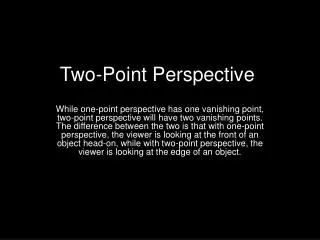
2 Point Perspective Graphic Communication
2 Point Perspective • Two views of a house are shown. Using VP1, VP2 and X as the lowest point, sketch a 2-point perspective view of this house. • A straight edge may be used. • Your sketch should be in good proportion • Do not show hidden detail X X VP2 VP1 X
Ground + Eaves Heights Start by drawing a ‘height line’ at point X and adding any building heights onto this line – roof, eaves, doors and window heights. These heights can be measured from the elevations given. X X VP2 VP1 Project the ground and eaves heights to each VP. Roof height Eaves height Lintel height Sill height Ground height X
Estimate Size of Building Decide how large the house is going to be. The sizes at this stage are ‘guessed’ but some common sense needs to be used. The elevation containing the door (without the roof) is square and the proportions of your drawing should reflect this. X X VP2 VP1 The side of this elevation is slightly longer than its height and again this information should be used in your ‘guess’. X
Centre Part of House Now that we have decided the size of this part of the building the rest of the shell can be drawn by projecting each of the corners to the VP’s. X X VP2 VP1 X
VP2 VP1 X Drawing First Gable The other visible part of the building is produced in the same way. X X Decide how far the building protrudes. It should look about half the width of the front part of the building. Decide how wide the building is. This part of the elevation should look square in proportion. Project the edges to the VP’s.
VP2 VP1 X Drawing Second Gable The third part of the building can now be constructed. In real life it is the same size as the part just drawn, but because you are drawing in perspective your drawing should actually have it slightly smaller. X X
VP2 VP1 X Finding Apex of Roof (1) To find the apex of the roof we can use a simple geometry technique. We know that the apex is in the centre of the elevation, so by drawing diagonal lines on the elevation we can accurately find the centre of the elevation. By projecting this point up until it crosses the projected line from VP1 we can find the apex point and draw the pitch of the roof X X Complete this part of the drawing by projecting the apex of the roof to VP2
VP2 VP1 X Finding Apex of Roof (2) Repeat this process to find the apex of the roof for the other visible elevation. X X To find the correct height of the apex of this roof it will be necessary to project the height from the height line along each of the elevations until it meets the elevation being worked on.
VP2 VP1 X Finding Apex of Roof (3) The final gable of the building is completed the same way as the two already done. X X Any gulley details where two or more roofs meet can also be added at this time.
VP2 VP1 X Outline of Building The building can now be darkened. X X Two lines from the elevation containing the front door have not been darkened because the step will stop all of these lines being seen. This will be dealt with later in the drawing.
Windows + Doors • The next process is to add any architectural detail such as windows and doors. The construction and hidden lines have been removed to make the drawing easier to understand, but some construction lines that will be used during this stage have not been deleted. • Using the height line, add projected lines across each of the elevations for the heights of doors and windows. X X VP2 VP1 X
First Window The windows and doors can now be drawn onto the elevations. Care should be taken when ‘guessing’ where the lines for these parts of the building are placed. X X VP2 VP1 In the case of this building the window on the gable is central on the wall. From the given elevations it can be calculated that the corner of the window is just outside where the diagonal lines pass at the top of the window. X
Second Window • The second window is also central on the wall. • On this occasion we should consider proportions. On the given elevation the window takes up about half of the width of the wall with the gap at each side equal. • In your drawing the perspective should be considered, and as the wall goes into the distance the sizes should be drawn slightly smaller. X X VP2 VP1 X
Third Window (1) The third window is also central on the wall. Using diagonal lines will locate the position of the centre of the window. X X VP2 VP1 X
Third Window (2) One side of the window is located, in this case the edge closer to the back of the house. By using some simple geometry techniques we can now calculate where the other side of the window should be drawn. X X VP2 VP1 • Draw diagonal lines across the window. • Project a line from VP2 through the centre of the diagonals until it cuts the join between the 2 windows. • Draw a diagonal line through both windows using the centre point. The point found is the near side of the window frame. X
Front Detail The front elevation is done in the same way as the others. The edge of the door is in line with the apex of the roof and this gives a good start point for finding the positions of the door and window. X X VP2 VP1 X
Step Detail The final part of the drawing to construct is the front step. Use the height line to get the correct height for the step. The rest of the construction is similar to the rest of the house. X X VP2 VP1 X
Outline of Building The final parts of the drawing can now be darkened. X X VP2 VP1 X
Final Drawing This is the final drawing of the house. X X VP2 VP1 X