Enhancing Flow Dynamics Through POD Filtering Method in Fluid Mechanics Experiments
Decompose the flow and retain top energy levels for detailed analysis. Utilize POD for filtering in experiments. Study poorly seeded jet holes with TR measurements. Explore endoscopes for 3D PIV setup. Analyze rotor positions for vorticity. Discover more in Lang et al.'s paper on transonic turbine testing. Implement TR-PIV in low-turbulent water flow experiments for intricate velocity measurements.

Enhancing Flow Dynamics Through POD Filtering Method in Fluid Mechanics Experiments
E N D
Presentation Transcript
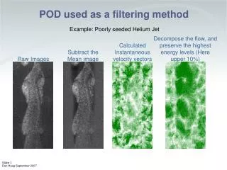
Decompose the flow, and preserve the highest energy levels (Here upper 10%) Calculated Instantaneous velocity vectors Subtract the Mean image Raw Images POD used as a filtering method Example: Poorly seeded Helium Jet
Holes in gappy dataset Poorly seeded TR measurements often have that POD as filtering POD Projection (90% of energy) Vectors Image
Example – a jet where the surrounding air has not been seeded POD as filtering
Two different endoscopes: Normal end 45 slanted end EndoscopesSetup for 3D PIV
Results Rotor - Position 1in-plane velocity Rotor - Position 1out-of--plane velocity Rotor-Position 1Instantaneous Vortivcity More details about the measurements in a transonic test turbine can be found in: Lang et al., "Stereoscopic particle image velocimetry in a transonic turbine stage", Experiments in Fluids 32, 2002, pp 700-709
Large area TR-PIV • Slow, low-turbulentwater flow • 60 µm polyamide particles • 20W AR-Ion laser w. scanning mirror • NanoSense camera • Frame rate ~100 Hz • Measuring distance 3.7m(1.2 m in water) • Measuring area820 x 1000 mmI.e. almost 1 m2 !!!
x/b=6.8 0.2 nm x/b=30.0 0.9 nm x/b=63.0 2.0 nm K. & C. Huenecke, Airbus Wingtip vortices, then and now Understanding tip vortices in details with PIV measurements in water 1962 CTA measurements in open air, waiting for the fly-by of the aircraft
Submerged PIV for large towing tank Cross section of HSVA tank Power supply on platform Towed aircraft model 10 m laser umbilical Laser housing on vertical traverse 1 - 6 m down
Vector Field Vorticity Click on the picture
Vector Field and Velocity Magnitude Click on the picture