Types of Memory Errors
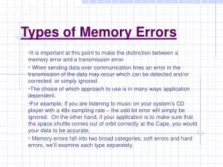
Types of Memory Errors. It is important at this point to make the distinction between a memory error and a transmission error. When sending data over communication lines an error in the transmission of the data may occur which can be detected and/or corrected or simply ignored.

Types of Memory Errors
E N D
Presentation Transcript
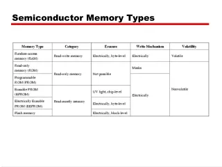
Types of Memory Errors It is important at this point to make the distinction between a memory error and a transmission error. When sending data over communication lines an error in the transmission of the data may occur which can be detected and/or corrected or simply ignored. The choice of which approach to use is in many ways application dependent. For example, if you are listening to music on your system’s CD player with a 48x sampling rate – the odd bit error will simply be ignored. On the other hand, if your application is to make sure that the space shuttle comes out of orbit correctly at the Cape, you would your data to be accurate. Memory errors fall into two broad categories, soft errors and hard errors, we’ll examine each type separately.
Soft Errors • Soft errors are unexpected or unwanted changes in the value of a bit (or bits) somewhere in the memory. • One bit may suddenly, randomly change state, or noise (electronic interference) may get stored as if it were valid data. • In either case, one or more bits become something other than what they are supposed to be, possibly changing an instruction in a program or a data value used by a program. • Soft errors result in changes in your data rather than changes in the hardware. Through replacement or restoring the erroneous data value (or program code) the system will once again operate exactly as it should. • Typically, a system reset (reboot - a cold boot) will effect this restore. • Soft errors are why you apply the old rule of thumb - "save often". Most soft errors result from problems within the memory chips themselves or in the overall circuitry of the system. The mechanism behind these two different types of soft errors is completely different.
Chip-Level Errors: • The errors which occur inside the memory chips themselves are almost always a result of radioactive decay. • The culprit is the epoxy of the plastic chip package, which like most materials contains a few radioactive atoms. • One of these minutely radioactive atoms will spontaneously decay and produce an alpha particle. • Practically every material will contain a few radioactive atoms, not enough to make the material radioactive (the material is well below background levels), but they are there. • By definition, a radioactive particle will spontaneously decay at some time. • An alpha particle consists of a helium nucleus, two protons and two neutrons, having a small positive charge and a lot of kinetic energy. If such a charged particle "hits" a memory cell in the chip, the charge and the energy of the particle will typically cause the cell to change state in a microscopic nuclear explosion. • The energy level of this nuclear explosion is too small to damage the silicon structure of the chip itself. • Whether a given memory cell will suffer this type of soft error is unpredictable.
However, when you deal with enough atoms this unpredictability becomes a probability, and chip designers can predict that one of the memory cells in a chip will suffer such an error. • They just can't predict which one of the cells will be affected. • In the early days of PCs, radioactive decay was the most likely cause of soft errors in the computer. • Improvements in design and technology have made memory chips more reliable. • For example, any given bit in a 16 KB chip might suffer a decay-based soft error every billion or so hours of operation. • The likelihood that a given bit in a modern 16 MB chip will suffer an error is on the order of once in two trillion hours of operation. • This makes modern chips about 5000 times more reliable than those in the first generation PCs, and the contents of each cell in the memory is about five million times more reliable when you consider that the capacities have increased about 1000 times. • Although conditions of use will obviously influence the occurrence of soft errors, the error rate of modern memory chips is such that the typical PC with 128 MB of RAM would suffer a decay-based soft error once in 10 to 30 years. This probability is so small that most manufacturers simply ignore this factor.
System-Level Errors: • Sometimes data traveling through the circuits of the computer gets hit by a noise glitch. • If a noise pulse is strong enough and occurs at an especially inopportune instant, it can be misinterpreted by the PC as a data bit. • Such a system-level error will have the same effect as a soft error in memory. • In fact, many such errors are reported as memory errors (glitch occurs between the memory and the memory controller, for example). The most likely place for system-level errors to occur is on the buses. • A glitch on a data line will cause the PC to try to use or execute a bad bit of data or program code, resulting in an error. • An error on the address bus will cause the PC to find the wrong bit or byte of data and the unexpected value might have the same results as if it were a data bus error. • The probability of a system-level soft error occurring depends almost entirely on the design of the PC. • Poor design can leave the system especially vulnerable to system-level error and may in fact assist in the generation of such errors. • Overclocking a system is a common cause of system-level soft errors.
Hard Errors • When some part of a memory chip actually fails, the result is a hard error. • One common cause of a hard error is a jolt of static electricity introduced into the system by someone carrying a static charge. • Initially, the hard error may appear to be a soft error (i.e., a memory glitch) however, rebooting the system does not alleviate the symptom and possibly the system will not reboot if it cannot pass the memory system self-test. • Hard errors require attention. Commonly the chip or module in which the error has occurred will require replacement. [Note: operating memory chips beyond their speed rating will commonly cause hard errors to occur - installing wait states in the memory cycles is an option allowed by many advanced setup procedures, but the better solution is to install faster memory.]
Detection and Prevention of Errors • Most PCs check every bit of memory every time you go through a cold boot operation (although this can be bypassed to save time). • Soft errors will not be caught by this check but hard errors should be. • Memory errors can be combated using two different techniques: parity and detection/correction. • Either technique will ensure the integrity of your system's memory, which is best - or whether you need it at all - is to some extent a personal or application dependent choice.
Parity • In the earlier days of PCs, memory chips were much less reliable than the current chips. • Memory manufacturers added an extra bit of storage to every byte of memory. • The extra bit was called a parity check bit and it allowed for verification of the integrity of the data stored in memory. • Using a simple algorithm, the parity bit allows the PC to determine that a given byte of memory has the correct number of 0s and 1s in it. • If the count changes, an error has been detected. • Whenever a byte is written to memory, the value stored in the parity bit is set to either a logical 1 or 0 in such a way that the total number of logical one bits in the nine bits is always odd. • Every time a byte is read from memory, the PC counts the number of logical 1 bits in the nine bits representing the byte and verifies that this total number is odd. • If the total number of logical 1 bits is even, then an error is detected in this byte. • Typically, a "Parity Check Error" message was reported to the monitor.
Today, many PC manufacturers have abandoned straight parity checking altogether. There are several reasons for this: • (1) Parity adds approximately 10-15% to the cost of memory in the PC. • (2) Parity checking steals vital space on the circuit boards, which is at a premium in today's compact systems. • (3) Increased reliability of the modern memory chip has rendered parity checking superfluous. Reliability has increased to the point that a PC with 128 MB of RAM will likely not see a soft error during its useful lifetime.
Fake Parity • Fake parity memory is a technique for cutting costs in memory modules for PCs that require memory with built-in parity checking. • Instead of actually performing the parity check, these modules always send out a signal indicating that the parity is correct. • To your PC, a memory module with fake parity appears no different than a module which internally actually checks the parity. • This fact allows memory manufacturers to produce fake parity memory modules (which are typically much cheaper to make) and place them in systems which require parity checking memory. • Fake parity has two downsides. • (1) The savings in cost is not passed on to the consumer, as the fake modules are often sold as ordinary parity modules with no indication that they use fake parity. • (2) The fake parity module does not protect your system from operating with bad data, since in reality no parity checking is done. • The only way to positively identify them is through the use of a SIMM tester • Kingston Technology (a memory chip vendor) has indicated that fake parity chips are commonly labeled with one of the following designations: BP, GSM, MPEC, or VT.
Detection and Correction • Parity checking can only detect the error of a single bit in a single byte. • The general approach to the detection and correction of soft errors in memory is illustrated in Figure below. More elaborate error-detection schemes can detect larger errors. Properly implemented, these techniques can fix single-bit errors without crashing the system. • Error Correction Code (or ECC)
Error Correction Code (or ECC) • In its most efficient form, requires three extra bits per byte of memory. As shown in Figure, the original data word is M bits long and there are an additional K bits added to the word that are used to detect and correct data bit errors. • The function f is simply the algorithm used to properly set the additional K bits. • The additional bits allow the system to detect the presence of an error and to locate and reverse a single bit error. [Note that some will refer to this technology by the acronym EDAC for Error Detection And Correction.] • IBM uses ECC on mainframe computers and high-end PCs used as network file servers. • As PC memory systems expand, the extra expense of ECC technology will be justified. • As the width of the data bus continues to expand, ECC memory will be less expensive to implement.
SECDED (Single Error Correction - Double Error Detection) • Is a commonly used technique in many current memory systems. The underlying principle behind this technique is still the parity bit but in this case multiple parity bits are used in an overlapping fashion to be able to isolate which bit is in error to allow for correction. • This technique is known as Hamming codes or Hamming functions.
Hamming Codes and SECDED Codes • Hamming Codes • One of the simplest forms of error correction is the Hamming Code developed by Richard Hamming of Bell Laboratories. • Hamming codes are capable of correcting single bit errors in a memory word. • Techniques that correct single bit errors in data are called SEC codes (Single Error Correction codes). • An extension to Hamming codes, called SECDED (Single Error Correction - Double Error Detection) allows for correction of single bit errors and the detection of double bit errors in a memory word. • SEC codes alone cannot detect double bit errors and will report an error free memory word if two bit errors have occurred. • Similarly, SECDED can correct single errors and detect double errors but will not be able to correct double bit errors nor detect triple bit errors. • SECDED counts on the fact that three bit errors occurring in a single word is so small that it is essentially impossible (but unfortunately - not entirely impossible).
Hamming codes add a group of parity bits (also called check bits) to the original data word. • How this is done is most easily viewed if the parity bits and the original data bits are distributed throughout the modified data word in the following fashion: • from a set of bits numbered 1 through 2 k-1, the bits whose numbers are powers of two are reserved for parity bits, where parity bit Pj is in bit position j = 2i, for some integer i = 0, 1, .... • A Hamming code generator accepts the data bits, places them in the bit positions with indices which are not powers of two, and computes the parity bits according to the following scheme. • The binary representation of the position number j is jk-1 ... j1 j0. • The value of parity bit P2i is chosen to give odd (or even) parity over all bit positions j such that ji= 1. • For example, bit position 4 = 22 will contain a parity bit that makes the parity odd over all bit positions that have the "4" bit turned on in their binary indices. • Thus each bit of the data word participates in several different parity bits.
Even Parity Case: • Suppose our data string consists of 4 bits = [1110]. This will require 3 parity bits in positions 20 = 1 = P1, 21 = 2 = P2, and 22 = 4 = P4. • The data bits will be divided into positions 3, 5, 6, and 7 (labeled D3, D5, D6, and D7). So the modified memory word looks like [P1 P2 D3 P4 D5 D6 D7]. We will also assume even parity. • Placing the data into this word produces [P1 P2 1 P4 1 1 0]. • Calculation of the parity bits is as follows: P1 = (D3, D5, D7) = (1 1 0), since the parity of these three bits is currently even, the parity bit P1 is set to 0 to make the parity across (P1 D3 D5 D7) even. The memory word then becomes: [0 P2 1 P4 1 1 0]. • Next, parity bit P2 is determined from data bits, P2 = (D3, D6, D7) = (1 1 0), since these three bits have even parity, the parity bit P2 must be set "off" (set to 0) so that the parity across (P2 D3 D6 D7) is even. The memory word then becomes [0 0 1 P4 1 1 0]. • Finally, parity bit P4 = (D5, D6, D7) = (1 1 0), again these bits have even parity, so the parity bit P4 = 0 to give even parity across (P4 D5 D6 D7). • The final memory word with the parity bits in place is: [0 0 1 0 1 1 0]. This "word" is what is stored in memory and subsequently retrieved by the memory system.
Overall Odd Parity: • Using the same example as above, now we assume that the overall parity is to be odd. • Placing the data into this word produces [P1 P2 1 P4 1 1 0]. • Calculation of the parity bits is as follows: P1 = (D3, D5, D7) = (1 1 0), since the parity in these three bits is even (there are two "on" bits) the parity bit needs to be set to 1 to make the parity across (P1 D3 D5 D7) be odd. Thus P1 = 1. The memory word then becomes [1 P2 1 P4 1 1 0]. • Next parity bit P2 is determined from data bits, P2 = (D3, D6, D7) = (1 1 0), since the parity in these bits is currently even, P2 must be set "on" so that the parity across (P2 D3 D6 D7) is odd. The memory word then becomes [1 1 1 P4 1 1 0]. • Finally, parity bit P4 will be set to 1 since P4 = (D5 D6 D7) = (1 1 0) which is even parity so to give odd parity across (P4 D5 D6 D7) P4 must be 1. • The final memory word with the parity bits in place is:[1 1 1 1 1 1 0]. This "word" is what is stored in memory and subsequently retrieved by the memory system.
At the time of retrieval the parity is checked to determine if the word retrieved matches the word that was stored. • This is done through the use of a check word (also called a syndrome word). • Each parity bit at the time of retrieval is checked against the value of the parity that was stored - if the two values do not match the corresponding check bit in the check word is set "on", otherwise it is set "off". • If there are no parity errors the parity bits are stripped off and the data word is sent to the processor. • If there is a parity error, then an error correction routine must be invoked that will correct the bit in error, then the parity bits are stripped off and the data word is sent to the processor.
Example: • Suppose that upon retrieval the memory word has a value [1 0 1 1 0 1 0]. It’s initial value being [1 0 1 1 0 1 1]. Also assume odd parity. • In other words the bit in position D7 is in error. • Upon retrieval the value of the check bits are set depending upon the value of the corresponding parity bit and the data bit values that are retrieved. P1 = 1 and (D3 D5 D7) = (1 0 0) which is odd parity so P1 should be 0 to indicate this but is in fact equal to 1. • This is a mismatch between what P1 is and what the check says P1 should be - thus C1 is set to 1 (indicating the mismatch between the parity bit and the retrieved value). • A similar technique is used to determine the values of C2 and C4. In this example - these values are: P2 = 0 and (D3 D6 D7) = (1 1 0) which is even indicating that P2 should be "on" but it is in fact "off" so C2 is set "on" indicating the mismatch. P4 = 1 and (D5 D6 D7) = (0 1 0) which is odd indicating that P4 should be "off" but it is in fact "on" again this is a mismatch so C4 is set "on". • Thus the check word [C4 C2 C1] has a value of [1 1 1] indicating that an error has been detected in position D7 - so the bit in D7 will be inverted and the parity bits stripped off. • Thus the value of the data word returned to the processor will be 1011 just as it was stored.
There are several properties that the syndrome word should have if error correction (and later double error detection) is to be handled efficiently: • If the syndrome contains all 0s, no error has occurred. • If the syndrome contains one and only one bit set to 1, then an error has occurred in one of the 4 check bits and not in the data word itself. • If the syndrome contains more than one bit set to 1, then the numerical value of the syndrome indicates the position of the data bit which is in error. • This data bit can then be inverted for correction. • To achieve these characteristics, the data and the check bits are arranged into a 12-bit word as we previously did with our four-bit word examples. • Bit positions in the word are numbered from 1 to 12 (the zero bit will be used for SECDED codes). • Those bit positions whose position numbers are powers of 2 are designated as the check bits.
The modified word looks like (bit positions that are powers of 2 are highlighted – these are the check bit positions):
The data bits are shown if the form: Dx/y where x is the bit position in the original memory word and y is the bits position in the augmented memory word. • The check bit values are calculated as follows (where indicates the XOR operation):C1 = D3 D5 D7 D9 D11 [bits 3, 5, 7, 9, and 11 all have “1” bit on]C2 = D3 D6 D7 D10 D11 [bits 3, 6, 7, 10, and 11 all have “2” bit on]C4 = D5 D6 D7 D12 [bits 5, 6, 7 and 12 all have “4” bit on]C8 = D9 D10 D11 D12 [bits 9, 10, 11, and 12 all have “8” bit on] • As shown, each check bit operates on every data bit position whose position number contains a 1 in the corresponding column position. Thus, data bit positions 3, 5, 7, 9, and 11 all contain the term 20; bit positions 3, 6, 7, 10, and 11 all contain the term 21; bit positions 5, 6, 7, and 12 all contain the term 22; and bit positions 9, 10, 11, and 12 all contain the term 23. A slightly different view of this is that bit position n is checked by those bits Ci such that i = n. For example, bit position 7 is checked by bits in positions 4, 2, and 1; and 7 = 4 + 2 + 1.
SECDED Codes • SECDED coding extends the functionality of Hamming codes beyond the detection and correction of single bit errors to include the detection (but not correction) of double bit errors. • This extension takes the form of adding a single parity bit in the P0 position of the memory "word". • This P0 parity bit is set so that the overall parity of every bit in the memory word, including all other parity bits, is odd (or even if even parity is used). • If a single bit is in error the Hamming code checks will determine the exact bit which is in error. • Detecting two bits in error works as follows: if two bits are in error then the Hamming code check word will indicate an error (note: the error position however will be incorrectly calculated since two bits are in error) and the parity bit P0 will indicate no parity error overall. • If a single bit error has occurred the Hamming code check word will indicate an error and so will the overall parity error bit P0. • If two bit errors have occurred, the overall parity will be indicated as correct - but the Hamming code check will indicate an error.
SECDED coding is relatively more efficient as the size of the memory word increases. • The number of bits needed for the parity system increases roughly as log2 of the number of data bits.
Beyond Single Bit Error Correction • We have been dealing exclusively with error detection and correction schemes that apply specifically to the storage of data in semiconductor memory chips. • This type of error occurs randomly within the memory and, as we have mentioned, occurs with extremely small probability. • The continued increase in the number of bits in memory and the continued decrease in the space occupied by those bits is sufficient justification for the overhead of SECDED coding of the memory. • Most modern DRAM includes SECDED coding and logic. • With serial transmission of data, the assumptions that we have been working under, namely that errors are independent of others, breaks down. • At high bandwidth transmission rates, a momentary disturbance in a single serial channel will easily cause several successive bits to be wrong. • Parity based codes, like the SECDED codes, are not nearly as useful in this situation.
To handle what are termed burst errors (a sequence of contiguous bits in error), more complex codes such as cyclic-redundancy check (or CRC codes) are employed. • The theory of operation of CRC codes goes way beyond what we want to consider here, but in practice they are fairly straightforward to implement. • Basically, a CRC generator consists of a shift register, some XOR gates, and a generating polynomial associated with the particular CRC that is used. • To use a CRC code, a number of data words are reformatted into a serial stream of bits. • As the bits are sent out, the transmitter computes the CRC by applying all bits to the shift register CRC generator. • When all bits have been transmitted, the transmitter appends the CRC bits to the data and sends them as well. • The receiver independently generates is own version of the CRC for the data bits it receives and compares it to the transmitted CRC. • If an error has occurred the receiver reports the error to the transmitter, so that it can retransmit the data.
As the above scenario implies, CRC codes have only the ability to detect errors in the transmission; They do not have the capability of correcting any error. • The length of the string of bits that are checked by a CRC code is arbitrarily long. • The tradeoff is that the longer the stream of bits that is checked, the longer will be the stream that must be retransmitted if an error is discovered. • The probability that the check will succeed even though some bits are in error depends upon the number of bits checked and the generating polynomial that is used. • Through proper selection of the generating polynomial CRC codes will: • Detect all single bit errors in the data stream • Detect all double bit errors in the data stream • Detect any odd number of errors in the data stream • Detect any burst error for which the length of the burst is less than the length of the generating polynomial • Detect most all larger burst errors