Download
1 / 12
140 likes | 352 Vues
Mare Srbinovska, Cvetan Gavrovski, Vladimir Dimcev, Zivko Kokolanski Department of Electrical Measurement and Materials, Faculty of Electrical Engineering and Information Technologies, Skopje, Macedonia E-mail: mares@etf.ukim.edu.mk. PC-Based RLC Meter. Introduction

E N D
Mare Srbinovska, Cvetan Gavrovski, Vladimir Dimcev, Zivko Kokolanski Department of Electrical Measurement and Materials, Faculty of Electrical Engineering and Information Technologies, Skopje, Macedonia E-mail:mares@etf.ukim.edu.mk PC-Based RLC Meter
Introduction Two measurement techniques: Step response Sinusoidal response Relaxation oscillator Experimental results Conclusions OUTLINE
Popular method that converts resistance, capacitance or inductance into corresponding voltage, time intervals or frequency. Two basic techniques for R, L and C measurement are called “Step response” and “Frequency domain” methods. This paper describes how we developed a Virtual RLC meter, based on a PC with a DAQ board (National Instruments PCI 6221) and an external relaxation oscillator, using Lab VIEW as the development software Introduction
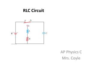
Step response Fig.1 RC and RL circuits An unknown capacitor or inductor whose value is to be determined can be connected to a known resistor in the appropriate circuit. The time constant of the circuit can be measured and the unknown component value computed. for the RC circuit for the RL circuit
Relaxation Oscillator The oscillator circuit consists of a comparator with a positive feedback loop, which converts the time – varying signal into a square wave with a varying time period. This signal can be counted and digitized into a value that is proportional to the oscillator frequency and in turn proportional to R, C or L measured. Fig.2 Relaxation oscillator For measurement of L, the resistor is known or vice versa For measurement of C, the resistor is known or vice versa
Hardware and Software realization The designed virtual RLC meter consists of the following blocks: the relaxation oscillator, data acquisition system, personal computer and Labview software. The designed virtual RLC meter has tree operation modes for R, L and C measurement respectively. The software of the RLC meter was entirely developed using Lab VIEW. Programming an application in Lab VIEW is very different from programming in a text based language such as C or Basic. Lab VIEW uses graphical symbols (icons) to describe programming actions. Fig.3 Block diagram of Virtual RLC meter
Software realization – Frequency setup The starting edge parameter is used to determine if the counter will begin measuring on a rising or falling edge.
Software realization The software of the RLC meter was entirely developed using Lab VIEW.For frequency measurement is used one counter on a Counter Input Channel. The edge, minimum value and maximum value are all configurable. The measurement edge is used to specify the edge on which the counter has started measuring. Result for the measured resistance Fig.4 Front panel of the frequency measurement
Experimental results – Measurement of R The first error is calculated using the operational amplifier TL, while is calculated by using higher performance comparator OP27. As it can be seen errors can be lower using OP27. The first error is calculated using the operational amplifier TL, while is calculated by using higher performance comparator OP27. As it can be seen errors can be lower using OP27.
Experimental results - Measurement of C The first error is calculated using the operational amplifier TL, while is calculated by using higher performance comparator OP27. As it can be seen errors can be lower using OP27.
This approach offers a simple solution for an application that needs the low cost measurement of resistors, capacitors and inductors. The realized virtual system can be used to any applications where frequency-time parameters have to be measured with highest resolution and programmable accuracy. Using a relaxation oscillator with higher performance comparator would significantly improve the performance and precision of this RLC meter. Conclusion