RLC Circuits
RLC Circuits . Ryan Dickmann. RLC Basics. An RLC Circuit is comprised of at least one resistor, one inductor, and one capacitor.

RLC Circuits
E N D
Presentation Transcript
RLC Circuits Ryan Dickmann
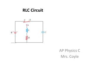
RLC Basics • An RLC Circuit is comprised of at least one resistor, one inductor, and one capacitor. • They act similarly to LC circuits in that the current tends to oscillate, but the oscillation is damped due to energy being “lost” in thermal energy through the resistor.
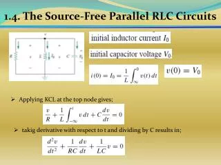
Finding the equation • RLC circuits can be in any configuration, but it is easiest to study them when all components are in a simple series configuration. • Using Kirchhoff’s voltage law: + + = = = We see that this has become a differential equation of the second-order.
Solving the equation = If there is no power source = Solve using a characteristic equation The final solution has a different form depending on the sign of the determinant but we will only consider the case where it is < 0
Solving cont. For y = Cetcos ( where C and are determined by initial values In this example: q = Qetcos ( (The values in the square root are swapped because the difference was assumed to be negative)
We assumed that the determinant was less than 0 because that is the case in which oscillation occurs. • For= = • Damping factor, , oscillation occurs for • This graph shows other cases
Forced oscillation • If the RLC circuit is connected to a AC power source with v(t) = Vsin(𝜔dt) • Thecircularly oscillating power source can resonate with the oscillation caused by the RLC. • i = Isin(𝜔dt - )
Force Oscillation Cont. • i = I sin(𝜔dt - ) • For the resistor, current and voltage are in phase. • For the inductor and the capacitor, current and voltage are 90 degrees off phase (in opposite directions) • Vt2= VR2+ (VL – VC)2 • Vt2= (IR)2+ (IXL– IXC)2 • XC = , XL= L
Forced Oscillation Cont. • Vt2= (IR)2+ (IXL – IXC)2 can be rearranged to • I = • Z = is the impedance of the circuit • I = • Phase constant: • tan =
Applications • In communications electrons, all three components are needed to make either a band-pass or a band reject. • RLC circuits can be used as oscillators usually when the resistance is low enough for it to be considered just as RL circuit. • Pulse discharge circuit: if the damping factor is > 1 the circuit is called overdamped. In an overdamped circuit all charge is lost before oscillation begins. This charge can provide a pulse much like a lone capacitor would.