RLC Circuits and Resonance
1.51k likes | 4.5k Vues
DC/AC Fundamentals: A Systems Approach. RLC Circuits and Resonance. Thomas L. Floyd David M. Buchla. Chapter 13. Ch.13 Summary. Series RLC Circuits.

RLC Circuits and Resonance
E N D
Presentation Transcript
DC/AC Fundamentals: A Systems Approach RLC Circuits and Resonance Thomas L. Floyd David M. Buchla Chapter 13
Ch.13 Summary Series RLC Circuits When a circuit contains an inductor and capacitor in series, the reactance of each opposes (i.e., cancels) the other. Total series LC reactance is found using: The total impedance is found using: The phase angle is found using:
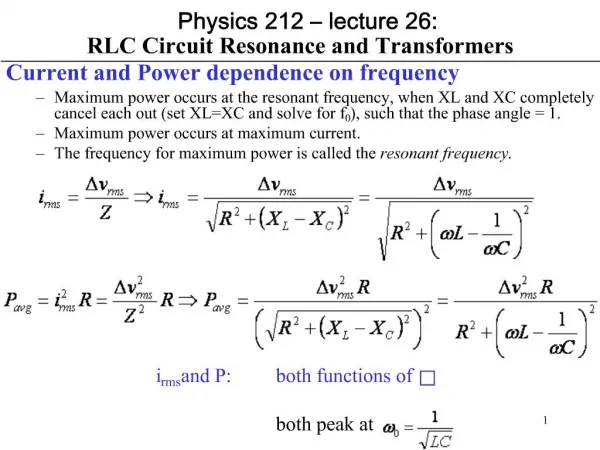
Ch.13 Summary XL and XC Vs. Frequency A series RLC circuit can be capacitive, inductive, or resistive, depending on the frequency. XC > XL XL > XC The frequency where XC=XL is called the resonant frequency. Reactance Below the resonant frequency, the circuit is predominantly capacitive. XC XL XC = XL Above the resonant frequency, the circuit is predominantly inductive. f Series resonance
Ch.13 Summary Series RLC Circuit Impedance What is the total impedance and phase angle of the series RLC circuit below? The total reactance is 3.16 kW The total impedance is 71.6o The phase angle is The circuit is capacitive, and I leads V by 71.6o.
Ch.13 Summary Series RLC Circuit Impedance What is the magnitude of the impedance for the circuit below? 753 W
Ch.13 Summary Series RLC Circuit Impedance Depending on the frequency, the circuit can appear to be capacitive or inductive. The circuit in the previous slide was capacitive because XC > XL. X XL XC XC XL f 100 kHz
Ch.13 Summary Series RLC Circuit Impedance What is the total impedance for the circuit when the frequency is increased to 400 kHz? 786 W The circuit is now inductive.
Ch.13 Summary Impedance of Series RLC Circuits By changing the frequency, the circuit in the previous slide inductive (because XL> XC). X XL XL XC XC f 400 kHz
Ch.13 Summary Series RLC Circuit Voltages The voltages across the RLC components must add to the source voltage in accordance with KVL. Because of the opposite phase shift due to L and C, VL and VC effectively subtract. Notice that VC is out of phase with VL. When they are algebraically added, the result is…. VL VC This example is inductive.
Ch.13 Summary Series Resonance Algebraic sum is zero. At series resonance, XC and XL cancel. VC and VL also cancel because they are equal in magnitude and opposite in polarity. The circuit is purely resistive at resonance.
Ch.13 Summary Series Resonance A formula for resonance can be found by assuming XC = XL and solving. The result is: What is the resonant frequency for the circuit? 196 kHz
Ch.13 Summary Series Resonance 5.0 Vrms Ideally, at resonance the sum of VL and VC is zero. By KVL, VR = VS VS 0 V What is VR at resonance? 5.0 Vrms
Ch.13 Summary Series RLC Circuit Impedance The general shape of the impedance versus frequency for a series RLC circuit is superimposed on the curves for XL and XC. Notice that at the resonant frequency, the circuit is resistive, and Z = R. X XL Z XC Z = R f Series resonance
Ch.13 Summary Series Resonance Summary of important concepts for series resonance: • Capacitive and inductive reactances are equal. • Total impedance is a minimum and is resistive. • The current is maximum. • The phase angle between VS and IS is zero. • fris calculated using:
Ch.13 Summary Series Resonant Filters Series resonant circuits can be used as filters. A band-pass filter allows signals within a range of frequencies to pass. Vout Circuit response Resonant circuit L C Vin Vout R f Series resonance
Ch.13 Summary Series Resonant Filters The response curve has a peak; meaning the current is maximum at resonance and falls off at frequencies below and above resonance. The maximum current (at resonance) develops maximum voltage across the series resistor(s). I or Vout The bandwidth (BW) of the filter is the range of frequencies over which the output is equal to or greater than 70.7% of its maximum value. f1 and f2 are commonly referred to as the criticalfrequencies, cutoff frequencies or half-power frequencies. Passband 1.0 0.707 f f1 fr f2 BW
Ch.13 Summary Decibels Filter responses are often described in terms of decibels (dB). The decibel is defined as: Example: When output power is half the input power, the ratio of Pout/Pin = ½, and When circuit input and output voltages are known, the filter response can be calculated using:
Ch.13 Summary Selectivity Selectivity describes the basic frequency response of a resonant circuit. (The -3 dB frequencies are marked by the dots.) Greatest Selectivity Medium Selectivity Least Selectivity The greater the Q of a filter at a given resonant frequency, the higher it’s selectivity. 0 f BW1 Which curve represents the highest Q? BW2 The one with the greatest selectivity. BW3
Ch.13 Summary Series Resonant Filters By taking the output across the resonant circuit, a band-stop (or notch) filter is produced. Circuit response Vout Stop band R 1 Vin Vout 0.707 L Resonant circuit C f f1 fr f2 BW
Ch.13 Summary Conductance, Susceptance, and Admittance Conductance is the reciprocal of resistance. Susceptance is the reciprocal of reactance. Admittance is the reciprocal of impedance. Conductance, susceptance, and admittance were defined in Chapter 10 as the reciprocals of resistance, reactance and impedance. As a review:
Ch.13 Summary Parallel RLC Circuit Impedance The admittance can be used to find the impedance. Start by calculating the total susceptance: The admittance is given by: The impedance is the reciprocal of the admittance: The phase angle is:
Ch.13 Summary Parallel RLC Circuit Impedance What is the total impedance of the parallel RLC circuit below? First, determine the conductance and total susceptance as follows: The total admittance is: 881 W
Ch.13 Summary AC Response of Parallel RLC Circuits The total current is given by: IC A typical current phasor diagram for a parallel RLC circuit is shown. +90o IR The phase angle is given by: -90o IL
Ch.13 Summary Parallel RLC Circuit Currents The currents in the RLC components must add to the source current in accordance with KCL. Because of the opposite phase shifts of IL and IC (relative to VS) they effectively subtract. Notice that IC is out of phase with IL. When they are algebraically added, the result is…. IC IL
Ch.13 Summary Parallel RLC Circuit Currents 20 mA 10 mA 0 mA 10 mA 20 mA Draw a diagram of the phasors having values of IR = 12 mA, IC = 22 mA and IL = 15 mA. IC • Set up a grid. IR • Plot the currents on the appropriate axes. • Combine the reactive currents. • Use the total reactive current and IR to find • the total current. IL In this case, Itot = 16.6 mA
Ch.13 Summary Parallel Resonance The algebraic sum is zero. Ideally, IC and IL cancel at parallel resonance because they are equal and opposite. Thus, the circuit is purely resistive at resonance. IC Notice that IC is out of phase with IL. When they are algebraically added, the result is…. IL
Ch.13 Summary Parallel Resonance (ideal case) The formula for the resonant frequency in both parallel and series circuits is the same: What is the resonant frequency for the circuit? 49.8 kHz
Ch.13 Summary Parallel Resonance in Non-ideal Circuits (non-ideal) In practical circuits, there is a small current through the coil at resonance and the resonant frequency is not exactly given by the ideal equation. The Q of the coil affects the equation for resonance: For Q >10, the difference between the ideal and the non-ideal formula is less than 1%, and generally can be ignored.
Ch.13 Summary Bandwidth of Resonant Circuits In a parallel resonant circuit, impedance is maximum and current is minimum. The bandwidth (BW) can be defined in terms of the impedance curve. Ztot Zmax A parallel resonant circuit is commonly referred to as a tank circuit because of its ability to store energy like a storage tank. 0.707Zmax f f1 fr f2 BW
Ch.13 Summary Parallel Resonance Summary of important concepts for parallel resonance: • Capacitive and inductive susceptance are equal. • Total impedance is a maximum (ideally infinite). • The current is minimum. • The phase angle between VS and IS is zero. • The resonant frequency (fr)is given by
Ch.13 Summary Parallel Resonant Filters Parallel resonant circuits can also be used for band-pass or band-stop filters. A basic band-pass filter is shown below. Vout R Passband 1.0 Vout Vin L C 0.707 Resonant circuit f Parallel resonant band-pass filter f1 fr f2 BW
Ch.13 Summary Parallel Resonant Filters For the band-stop filter, the positions of the resonant circuit and resistance are reversed as shown here. C Vout Stop band Vin Vout 1 L 0.707 R Resonant circuit f Parallel resonant band-stop filter f1 fr f2 BW
Ch.13 Summary Key Ideas for Resonant Filters A band-pass filter allows frequencies between two critical frequencies and rejects all others. • A band-stop filter rejects frequencies between two critical frequencies and passes all others. • Band-pass and band-stop filters can be made from both series and parallel resonant circuits. • The bandwidth of a resonant filter is determined by the Q and the resonant frequency. • The output voltage at a critical frequency is 70.7% of the maximum.
Ch.13 Summary Key Terms A condition in a series RLC circuit in which the reactances ideally cancel and the impedance is a minimum. Series resonance Resonant frequency (fr) The frequency at which resonance occurs; also known as the center frequency. Parallel resonance A condition in a parallel RLC circuit in which the reactances ideally are equal and the impedance is a maximum. Tank circuit A parallel resonant circuit.
Ch.13 Summary Key Terms Half-power frequency The frequency at which the output power of a resonant circuit is 50% of the maximum value (the output voltage is 70.7% of maximum); another name for critical or cutoff frequency. Decibel Ten times the logarithmic ratio of two powers. Selectivity A measure of how effectively a resonant circuit passes desired frequencies and rejects all others. Generally, the narrower the bandwidth, the greater the selectivity.
Ch.13 Summary Quiz • In practical series and parallel resonant circuits, the total impedance of the circuit at resonance will be • a. capacitive • b. inductive • c. resistive • d. none of the above
Ch.13 Summary Quiz 2. In a series resonant circuit, the current at the half-power frequency is a. maximum b. minimum c. 70.7% of the maximum value d. 70.7% of the minimum value
Ch.13 Summary Quiz X XL XC f f 3. The frequency represented by the red dashed line is the a. resonant frequency b. half-power frequency c. critical frequency d. all of the above
Ch.13 Summary Quiz 4. In a series RLC circuit, if the frequency is below the resonant frequency, the circuit will appear to be a. capacitive b. inductive c. resistive d. answer depends on the particular components
Ch.13 Summary Quiz 5. In a series resonant circuit, the resonant frequency can be found from the equation a. b. c. d.
Ch.13 Summary Quiz 6. In an ideal parallel resonant circuit, the total impedance at resonance is • zero • equal to the resistance • equal to the reactance • infinite
Ch.13 Summary Quiz 7. In a parallel RLC circuit, the magnitude of the total current is always the a. same as the current in the resistor. b. phasor sum of all of the branch currents. c. same as the source current. d. difference between resistive and reactive currents.
Ch.13 Summary Quiz 8. If you increase the frequency in a parallel RLC circuit, the total current a. will not change b. will increase c. will decrease d. can increase or decrease depending on if it is above or below resonance.
Ch.13 Summary Quiz • The phase angle between the source voltage and • current in a parallel RLC circuit will be positive if • a. IL is larger than IC • b. IL is larger than IR • c. both a and b • d. none of the above
Ch.13 Summary Quiz 10. A highly selectivity circuit will have a a. small BW and high Q. b. large BW and low Q. c. large BW and high Q. d. none of the above
Ch.13 Summary Answers 1. c 2. c 3. a 4. a 5. b 6. d 7. b 8. d 9. d 10. a