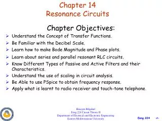
Resonance Circuits: Series and Parallel - Key Parameters & Applications
Explore series and parallel resonance circuits, including frequency, bandwidth, quality factor, and power calculations. Learn about how resonance is utilized in filters and practical applications.

Resonance Circuits: Series and Parallel - Key Parameters & Applications
E N D
Presentation Transcript
Content • Series Resonance • Parallel Resonance • Important Parameters • Resonance Frequency, ωo • Half-power frequencies, ω1and ω2 • Bandwidth, • Quality Factor, Q • Application
Introduction • Resonance is a condition in an RLC circuit in which the capacitive and reactive reactance are equal in magnitude, thereby resulting in a purely resistive impedance. • Resonance circuits are useful for constructing filters and used in many application.
At Resonance • At resonance, the impedance consists only resistive component R. • The value of current will be maximum since the total impedance is minimum. • The voltage and current are in phase. • Maximum power occurs at resonance since the power factor is unity.
Series Resonance Total impedance of series RLC Circuit is At resonance The impedance now reduce to The current at resonance
Resonance Frequency Resonance frequency is the frequency where the condition of resonance occur. Also known as center frequency. Resonance frequency
Half-power Frequency Half-power frequencies is the frequency when the magnitude of the output voltage or current is decrease by the factor of 1 / 2 from its maximum value. Also known as cutoff frequencies.
Bandwidth, Bandwidth, is define as the difference between the two half power frequencies. The width of the response curve is determine by the bandwidth.
Quality Factor (Q-Factor) The ratio of resonance frequency to the bandwidth The “sharpness” of response curve could be measured by the quality factor, Q.
Q-Factor Vs Bandwidth • Higher value of Q, smaller the bandwidth. (Higher the selectivity) • Lower value of Q larger the bandwidth. (Lower the selectivity)
High-Q It is to be a high-Q circuit when its quality factor is equal or greater than 10. For a high-Q circuit (Q ≥ 10), the half-power frequencies are, for all practical purposes, symmetrical around the resonant frequency and can be approximated as
Maximum Power Dissipated The average power dissipated by the RLC circuit is The maximum power dissipated at resonance where Thus maximum power dissipated is
Power Dissipated at ω1 and ω2 At certain frequencies, where ω = ω1 and ω2, the dissipated power is half of maximum power Hence, ω1 and ω2 are called half-power frequencies.
Example 14.7If R=2Ω, L=1mH and C=0.4 F, calculate • Resonant frequency, ωo • Half power frequencies, ω1 and ω2 • Bandwidth, • Amplitude of current at ωo, ω1 and ω2.
Solution Resonant frequency Bandwidth Quality Factor
Solution Since Q ≥10 , we can regard this as high-Q circuit. Hence
Solution Current, I at ω= ωo Current, I at ω = ω1 , ω2
Practice Problem 14.7 • A series connected circuit has R=4Ω and L=25mH. Calculate • Value of C that will produce a quality factor of 50. • Find ω1 , ω2 and . • Determine average power dissipated at ω=ωo , ω1andω2. Take Vm = 100V
Solution Value of C that will produce Q = 50 Bandwidth
Solution Since Q ≥10 , we can regard this as high-Q circuit. Hence
Solution Power dissipated at ω = ωo Power dissipated at ω = ω1 , ω2
Parallel Resonance The total admittance Resonance occur when
At Resonance • At resonance, the impedance consists only conductance G. • The value of current will be minimum since the total admittance is minimum. • The voltage and current are in phase.
Parameters in Parallel Circuit Parallel resonant circuit has same parameters as the series resonant circuit. Resonance frequency Half-power frequencies
Parameters in Parallel Circuit Bandwidth Quality Factor
Example 14.8If R=8kΩ, L=0.2mH and C=8F, calculate • ωo • Q and • ω1 and ω2 • Power dissipated at ωo, ω1 and ω2.
Solution Resonant frequency Bandwidth Quality Factor
Solution Since Q ≥10 , we can regard this as high-Q circuit. Hence
Solution Power dissipated at ω = ωo Power dissipated at ω = ω1 , ω2
Practice Problem 14.8 • A parallel resonant circuit has R=100kΩ, L=25mH and C=5nF. Calculate • ωo • ω1 and ω2 • Q •
Solution Resonant frequency Bandwidth Quality Factor
Solution Since Q ≥10 , we can regard this as high-Q circuit. Hence
PASSIVE FILTERS • A filter is a circuit that is designed to pass signals with desired frequencies and reject or attenuates others • A filter is a Passive Filters if it consists only passive elements which is R, L and C. • Filters that used resonant circuit • Bandpass Filter • Bandstop Filter
BANDPASS FILTER • A bandpass filter is designed to pass all frequencies within ω1ωo ω2
BANDPASS FILTER SERIES RLC CIRCUIT
BANDPASS FILTER PARALLEL RLC CIRCUIT
BANDSTOP FILTER • A bandstop or bandreject filter is designed to stop or reject all frequencies within ω1ωo ω2
BANDSTOP FILTER SERIES RLC CIRCUIT
BANDSTOP FILTER PARALLEL RLC CIRCUIT