Chapter 4 and 5 Time Varying Circuits
970 likes | 1.01k Vues
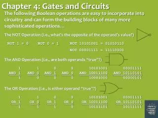
Capacitors. Inductors. Time Constant T C. Waveforms. RC Circuits – Step Input. RL Circuits – Step Input. Chapter 4 and 5 Time Varying Circuits. CAPACITORS:. Section 4.1. Dielectric Insulator = permittivity. A. A. C =. d. Metal plates of area ‘A’. d. Where:

Chapter 4 and 5 Time Varying Circuits
E N D
Presentation Transcript
Capacitors Inductors Time Constant TC Waveforms RC Circuits – Step Input RL Circuits – Step Input Chapter 4 and 5 Time Varying Circuits Grossman/ Melkonian
CAPACITORS: Section 4.1 Dielectric Insulator = permittivity A A C = d Metal plates of area ‘A’ d • Where: ‘C’ is the capacitance in Farads. The farad is a large unit. Typical values of capacitance are in F or pF. ‘’ is the permittivity of the dielectric medium (8.854x10⁻¹² F/m for air). ‘A’ is the cross-sectional area of the two parallel conducting plates. ‘d’ is the distance between the two plates. Grossman/ Melkonian
CAPACITORS: + + Dielectric Insulator = permittivity Vs Metal plates of area ‘A’ - - iC(t) iC(t) + + Standard Notations (passive sign convention) vC vC - - • When a voltage is applied to the plates, an electric field is produced that causes an electric charge q(t) to be produced on each plate. Grossman/ Melkonian
CAPACITORS: q (t) = CvC(t) Charge of a capacitor since: i(t) = dq(t)/dt and: q(t) = CvC(t) Differentiating: dq(t) = C•dvC(t) iC(t) = dq(t)/dt = C(dvC(t)/dt ) i-v relationship for a capacitor iC(t) = C[dvC(t)/dt] Grossman/ Melkonian
CAPACITORS: • Integrating the i-v relationship of the capacitor: t t dvC(t) = 1/CiC(t)dt = vC(t) • Letting VC(0) = V0 represent the initial voltage across the capacitor at some time t = t0: t Voltage across a capacitor vC(t) = V0 + 1/C iC(t)dt t 0 t0 iC (t) = C[dvC(t)/dt] Current through a capacitor Grossman/ Melkonian
CAPACITORS: • Capacitor Power: pC(t) = iC(t)•vC(t) = C[dvC(t)/dt]vC(t) pC(t) = d/dt[½CvC2(t)] Power associated with a capacitor • Capacitor Energy: Energy is the integral of power, therefore, wC(t) = ½CvC2(t) Energy associated with a capacitor Grossman/ Melkonian
CAPACITORS: Example 1: Given iC (t) = Io[e-t/Tc] for t 0 and vC(0) = 0V, find the capacitor’s power and energy. Power: pc(t) = iC(t)•vC(t) t t vC(t) = V0 + 1/C iC(x)dx = 0V + 1/C Io[e-x/Tc]dx 0 0 vc (t) = [(IoTc/C)(1-e-t/Tc)]V pC(t) = [Ioe-t/Tc][(IoTC/C)(1-e-t/Tc)]W vC(t) iC(t) Power can be positive or negative pc(t) = Io2Tc/C(e-t/Tc -e-2t/Tc) Grossman/ Melkonian
CAPACITORS: Example 1 cont.: Energy: wC(t) = ½CvC2(t) Energy is always positive wC(t) = [(IoTC)2/2C](1-e-t/Tc)2 Waveforms: iC(t) Io iC(t) = Io[e-t/Tc] t 0 Grossman/ Melkonian
CAPACITORS: Example 1 cont.: vC(t) IoTc/C vc(t) = [(IoTc/C)(1-e-t/Tc)]V t 0 pC(t) Io2Tc/4C pc(t) = Io2Tc/C(e-t/Tc -e-2t/Tc) t Tcln2 0 Grossman/ Melkonian
CAPACITORS: Example 1 cont.: wc (t) Io2Tc2/2C t 0 wC(t) = [(IoTC)2/2C](1-e-t/Tc)2 Grossman/ Melkonian
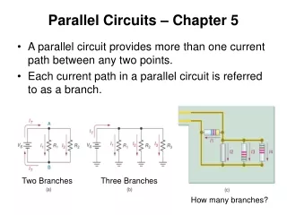
CAPACITORS: Series and Parallel Capacitors: Series: Capacitors connected in series combine like resistors connected in parallel. 1/CEQ = 1/C1 + 1/C2 + 1/C3 + 1/C4 +….+ 1/CN C1 C3 C2 + i(t) vc(t) C4 - C5 C7 C6 Grossman/ Melkonian
CAPACITORS: Series and Parallel Capacitors: Parallel: Capacitors connected in parallel add like resistors connected in series. CEQ = C1 + C2 + C3 + C4 + … + CN iC2(t) iC1(t) iC3(t) vc(t) . . . C1 C2 CN C3 C4 C5 Grossman/ Melkonian
CAPACITORS: Properties of the Capacitor: • The voltage across a capacitor cannot change instantaneously. • Current through a capacitor can change instantaneously. • The capacitor stores energy in its electric field. • The current through a capacitor is zero when the voltage across the capacitor is constant. For example, when the capacitor is fully charged. Therefore, a capacitor acts like an open circuit when a DC voltage is applied. • Capacitors in parallel add. • Capacitors in series combine like resistors connected in parallel. Grossman/ Melkonian
INDUCTORS: vL(t) + - iL(t) Magnetic Field Lines • Inductors are typically made by winding a coil of wire around an insulator or ferromagnetic material. • Current flowing through an inductor creates a magnetic field. i-v relationship for an inductor vL(t) = L[diL(t)/dt] • Where L is the inductance of the coil measured in henrys (H). 1 H = 1 V-s/A Grossman/ Melkonian
INDUCTORS: • The basic results for the inductor can be derived in the same way as we have done for the capacitor: t iL(t) = iL(0) + 1/L vL(t) dt Current through an inductor pL(t) = iL(t)•vL(t) = d/dt[WL(t)] Power associated with an inductor WL(t) = 1/2LiL2(t) Energy associated with an inductor Grossman/ Melkonian
INDUCTORS: Properties of the Inductor: • Inductor current is continuous. Cannot change instantaneously. (Would require infinite power). • The voltage across an inductor can change instantaneously. • When the current through an inductor is constant, the voltage is zero. Therefore, the inductor acts like a short circuit when a DC source is applied. • Inductors connected in series add like resistors connected in series. • Inductors connected in parallel combine like resistors connected in parallel Grossman/ Melkonian
TIME-DEPENDENT SIGNALS: Section 4.2 • Sources that produce currents or voltages that vary with time are called time-dependent signal sources. • The sinusoidal waveform is one of the most important time-dependent signals. + + V(t) i(t) ~ V(t), i(t) - - Sinusoidal source Generalized time-dependent signals Grossman/ Melkonian
TIME-DEPENDENT SIGNALS: • An important class of time-dependent signals is a periodic signal. • A periodic signal satisfies the following equation: x(t) = x(t + nT) n = 1, 2, 3, … where T is the period of the signal • A generalized sinusiod is defined as follows: x(t) = Acos(t + ) where f = natural frequency = 1/T cycles/s or Hz = radian frequency = 2f rad/s = 2t/T = 360t/T rad Grossman/ Melkonian
TIME-DEPENDENT SIGNALS: v(t) v(t) t t Damped sinusoid Square wave v(t) v(t) Pulse width t t Pulse train Sawtooth wave Grossman/ Melkonian
TIME-DEPENDENT SIGNALS: Sinusoidal Waveform Radial frequency Amplitude Phase shift x(t) = Acos(t + ) Time A T Reference cosine t A T Arbitrary sinusoid t t Grossman/ Melkonian
TIME-DEPENDENT SIGNALS: Root Mean Square • The average value of a sinusoidal signal is zero, independent of its amplitude and frequency. Therefore, another method must be used to quantify the strength of a time-varying signal. • The operation of computing the Root-Mean-Square of a waveform is a method for quantifying the strength of a time-varying signal. T Root-mean-square xrms = 1/T x2 (t) dt 0 Grossman/ Melkonian
TIME-DEPENDENT SIGNALS: Example 2: Calculate the rms value of the sinusoidal voltage v(t) = Vsin(t). T vrms = 1/T v2 (t) dt 0 T = 1/f = 2/ 2/ vrms = /2V2sin2(t)dt 0 2/ vrms = V2/21/2 - 1/2cos(2t)dt 0 Grossman/ Melkonian
TIME-DEPENDENT SIGNALS: Example 2 cont.: 2/ vrms = V2/2[t/2 - 1/4sin(2t)] 0 vrms = V2/2[(2/2 - /4sin(4/) – (0 – 0)] 0 vrms = V2/2(/ - /4sin(4) – 0) V vrms = vrms = 0.707V 2 Grossman/ Melkonian
RC CIRCUIT, STEP RESPONSE: Sections 4.3 (pgs 161 & 162), 5.1, 5.2, 5.3 • Assume we have the following series circuit containing a voltage source, a resistor, and a capacitor. How do we write an expression for the voltage across the capacitor? R Switch t = 0 iC(t) + + VT vC(t) C - - Grossman/ Melkonian
RC CIRCUIT, STEP RESPONSE: • Writing KVL for the circuit: – VS + Ric(t) + vC(t) = 0 ic(t) = C(dvc(t)/dt ) RC(dvC(t)/dt) + vC(t) = VS First order linear differential equation. RC(dvC(t)/dt) + vC(t) = VS for t 0 R Switch t = 0 iC(t) + + VS vC(t) C - - Grossman/ Melkonian
RC CIRCUIT, STEP RESPONSE: • Since the circuit is linear, we can separate the solution vC(t) into two components: vC(t) = vN(t) + vF(t) • Natural Response: 1. RC(dvN(t)/dt) + vN(t) = 0 t 0 Natural Response: VS = 0 • The classical approach to solving this type of an equation is to try a solution of the following form: vN(t) = Kest where K and s are constants Grossman/ Melkonian
RC CIRCUIT, STEP RESPONSE: • Substituting vN(t) = Kest into the above equation: RCsKest + Kest = 0 Kest(RCs + 1) = 0 K = 0 is trivial solution RCs + 1 = 0 Characteristic Equation • Solving the Characteristic Equation: s = -1/RC • Therefore, the Natural Response has the form: vN(t) = Ke-t/RC t > 0 Grossman/ Melkonian
RC CIRCUIT, STEP RESPONSE: • Forced Response: 2. RC(dvF(t)/dt) + vF(t) = VS t 0 Forced Response • Equation 2 requires the linear combination of vF(t) and its derivative equal a constant VS. Setting vF(t) = VS satisfies this condition. Combining the Natural and Forced Responses: vC(t) = vN(t) + vF(t) = Ke-t/RC + VSt > 0 (General Solution) • Evaluating K using initial conditions (at t=0, the voltage across the capacitor): v(0) = V0 = Ke0 + VS = K + VS This requires K = (V0 – VS) Grossman/ Melkonian
RC CIRCUIT, STEP RESPONSE: • Substituting into the general solution: vC(t) = (V0 – VS)e-t/RC + VSt > 0 Decaying exponentialConstant Important Values: RC: Defined as the time constant, sometimes written as TC or . The time constant depends only on fixed circuit parameters. V0: The initial condition or initial voltage across the capacitor. Sometimes written as Vi or vC(0) VS: The Thevenin voltage seen by the capacitor as t. Sometimes written as Vf or vC(). Grossman/ Melkonian
RC CIRCUIT, STEP RESPONSE: Important Values cont.: R: The Thevenin resistance or equivalent resistance seen by the capacitor. Sometimes written as RT. t(0-): The instant of time just prior to t=0 or the switch changing its position. t(0): The time t=0 or the instant the switch changes its position. t(0+): The instant of time just after t=0 or just after the switch changes its position. Grossman/ Melkonian
RC CIRCUIT, STEP RESPONSE: Important Concepts: • The voltage across a capacitor cannot change instantaneously. Therefore, vC(0-) = vC(0) = vC(0+). • The current through a capacitor can change instantaneously. • A capacitor acts like a short circuit the instant a voltage is applied across its terminals. • When a DC source is applied to a capacitor, it becomes an open circuit as t. vC(t) = (Vi – Vf)e-t/TC + Vft > 0 Grossman/ Melkonian
RL CIRCUIT, STEP RESPONSE: • Assume we have the following series circuit containing a voltage source, a resistor, and an inductor. We can write an expression for the current through the inductor using a similar procedure as that applied previously for finding the voltage across a capacitor. R Switch t = 0 iL(t) + + VT vL(t) L - - Grossman/ Melkonian
RL CIRCUIT, STEP RESPONSE: • Applying a similar procedure as that applied to finding the voltage across a capacitor, we obtain the equation for the current through an inductor when the input is a step function. iL(t) = (I0 – IS)e-Rt/L + ISt > 0 Decaying exponentialConstant Important Values: L/R: Defined as the time constant, sometimes written as TC or . The time constant depends only on fixed circuit parameters. I0: The initial condition or initial current through the inductor. Sometimes written as Ii or iL(0) IS: The Norton current seen by the inductor as t. Sometimes written as If or iL(). Grossman/ Melkonian
RL CIRCUIT, STEP RESPONSE: Important Values cont.: R: The Norton resistance or equivalent resistance seen by the inductor. Sometimes written as RN. t(0-): The instant of time just prior to t=0 or the switch changing its position. t(0): The time t=0 or the instant the switch changes its position. t(0+): The instant of time just after t=0 or just after the switch changes its position. Grossman/ Melkonian
RL CIRCUIT, STEP RESPONSE: Important Concepts: • The current through an inductor cannot change instantaneously. Therefore, iL(0-) = iL(0) = iL(0+). • The voltage across an inductor can change instantaneously. • A inductor acts like an open circuit the instant a voltage or current is applied to its terminals. • When a DC source is applied to a inductor, it becomes a short circuit as t. iL(t) = (Ii – If)e-t/TC + Ift > 0 Grossman/ Melkonian
RC CIRCUIT, STEP RESPONSE: Example 3: • Calculate the RC time constant (TC), Vi, Vf, the voltage across the capacitor, and the current through the capacitor for t > 0. The switch has been open for a long time before closing. 1.5K Switch t = 0 iC(t) + + 16V vC(t) 1.5F 1.5K - - Grossman/ Melkonian
RC CIRCUIT, STEP RESPONSE: Example 3 cont.: • RC time constant (TC): TC = RTH•CEQ = 1.5K 1.5K•1.5F TC = 1.125ms 1.5K Switch t = 0 iC(t) + + 16V vC(t) 1.5F 1.5K - - Grossman/ Melkonian
RC CIRCUIT, STEP RESPONSE: Example 3 cont.: Vi = 0V The capacitor has had time to discharge. 1.5K Vf = 16V Voltage divider 1.5K + 1.5K Vf = 8V Switch t = 0 1.5K iC(t) + + 16V vC(t) 1.5F 1.5K - - Grossman/ Melkonian
RC CIRCUIT, STEP RESPONSE: Example 3 cont.: vC(t) = (Vi – Vf)e-t/TC + Vft > 0 • vC(t) t > 0 vC(t) = (0V - 8V)e-t/TC + 8V t > 0 vC(t) = 8 - 8e-t/1.125msV t > 0 1.5K Switch t = 0 iC(t) + + 16V vC(t) 1.5F 1.5K - - Grossman/ Melkonian
RC CIRCUIT, STEP RESPONSE: Example 3 cont.: iC(t) = C[dvC(t)/dt] • iC(t) t > 0 iC(t) = 1.5F d/dt[8 - 8e-t/1.125ms]At > 0 iC(t) = 10.67e-t/1.125ms mA t > 0 Switch 1.5K t = 0 iC(t) + + 16V vC(t) 1.5F 1.5K - - Grossman/ Melkonian
RL CIRCUIT, STEP RESPONSE: Example 4: • Calculate the L/R time constant (TC), Ii, If, the current through the inductor, and the voltage across the inductor for t > 0. The switch has been closed for a long time. 5K 1K Switch t = 0 iL(t) + + 14V 3k 5mH vL(t) - - Grossman/ Melkonian
RL CIRCUIT, STEP RESPONSE: Example 4 cont.: • L/R time constant (TC): 5mH TC = LEQ/RN = 3k + 1K TC = 1.25s 1K Switch t = 0 5K iL(t) + + 14V 3k 5mH vL(t) - - Grossman/ Melkonian
RL CIRCUIT, STEP RESPONSE: Example 4 cont.: 1/1K Source transformation and current divider 2.8mA Ii = 1/5K + 1/3k + 1/1K If = 0A Ii = 1.83mA 5K 1K Switch t = 0 iL(t) + + 14V 3k 5mH vL(t) - - Grossman/ Melkonian
RL CIRCUIT, STEP RESPONSE: Example 4 cont.: iL(t) = (Ii – If)e-t/TC + Ift > 0 • iL(t): iL(t) = (1.83 - 0)e-t/1.25s+ 0 mAt > 0 iL(t) = 1.83e-t/1.25s mAt > 0 5K 1K Switch t = 0 iL(t) + + 14V 3k 5mH vL(t) - - Grossman/ Melkonian
RL CIRCUIT, STEP RESPONSE: Example 4 cont.: • vL(t): vL(t) = L[diL(t)/dt] vL(t) = 5mH•d/dt[1.83x10-3•e-t/1.25s]V vL(t) = - 7.32e-t/1.25s V t > 0 5K 1K Switch t = 0 iL(t) + + 14V 3k 5mH vL(t) - - Grossman/ Melkonian
RC CIRCUIT, STEP RESPONSE: Example 5 : • The switch has been in position ‘A’ for a long time. At t=0, the switch moves to position ‘B’. Calculate Vi, Vf, TC, and vC(t), iC(t), and iR(t) for t > 0. 800 t = 0 A iC(t) B iR(t) + + + vC(t) 2F 10V 6V 400 - - - Grossman/ Melkonian
RC CIRCUIT, STEP RESPONSE: Example 5 cont.: 400 Vi = 10V Vi = 3.34V Voltage divider 800 + 400 400 Vf = 6V Vf = 2V Voltage divider 800 + 400 800 t = 0 A iC(t) B iR(t) + + + vC(t) 2F 10V 6V 400 - - - Grossman/ Melkonian
RC CIRCUIT, STEP RESPONSE: Example 5 cont.: • TC: TC = RTH•CEQ = 800 400•2F TC = 533.4 s 800 t = 0 A iC(t) B iR(t) + + + vC(t) 2F 10V 6V 400 - - - Grossman/ Melkonian
RC CIRCUIT, STEP RESPONSE: Example 5 cont.: • vC(t) t > 0 vC(t) = (Vi – Vf)e-t/TC+ Vft > 0 vC(t) = (3.34V - 2V)e-1875t + 2V t > 0 vC(t) = 2 + 1.34e-1875t V t > 0 800 t = 0 A iC(t) B iR(t) + + + vC(t) 2F 10V 6V 400 - - - Grossman/ Melkonian
RC CIRCUIT, STEP RESPONSE: Example 5 cont.: iC(t) = C[dvC(t)/dt] • iC(t) t > 0 iC(t) = 2F d/dt[2 + 1.34e-1875t]At > 0 iC(t) = -5.01e-1875tmA t > 0 800 t = 0 A iC(t) B iR(t) + + + vC(t) 2F 10V 6V 400 - - - Grossman/ Melkonian