Chapter 20: Circuits
Chapter 20: Circuits. Current and EMF Ohm’s Law and Resistance Electrical Power Alternating Current Series and Parallel Connection Kirchoff’s Rules and Circuit Analysis Internal Resistance Capacitors in Circuits. Current and EMF. A few definitions:

Chapter 20: Circuits
E N D
Presentation Transcript
Chapter 20: Circuits • Current and EMF • Ohm’s Law and Resistance • Electrical Power • Alternating Current • Series and Parallel Connection • Kirchoff’s Rules and Circuit Analysis • Internal Resistance • Capacitors in Circuits
Current and EMF A few definitions: • Circuit: A continuous path made of conducting materials • EMF: an alternative term for “potential difference” or “voltage,” especially when applied to something that acts as a source of electrical power in a circuit (such as a battery) • Current: the rate of motion of charge in a circuit: Symbol: I (or sometimes i). SI units: C/s = ampere (A)
Current and EMF “Conventional current:” assumed to consist of the motion of positive charges. Conventional current flows from higher to lower potential.
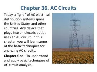
Current and EMF Direct current (DC) flows in one direction around the circuit Alternating current (AC) “sloshes” back and forth, due to a time-varying EMF that changes its sign periodically
Chapter 20: Circuits • Current and EMF • Ohm’s Law and Resistance • Electrical Power • Alternating Current • Series and Parallel Connection • Kirchoff’s Rules and Circuit Analysis • Internal Resistance • Capacitors in Circuits
Ohm’s Law and Resistance The current that flows through an object is directly proportional to the voltage applied across the object: A constant of proportionality makes this an equation:
Ohm’s Law and Resistance The constant of proportionality, R, is called the resistance of the object. SI unit of resistance: ohm (W)
Ohm’s Law and Resistance Resistance depends on the geometry of the object, and a property, resistivity, of the material from which it is made: Resistivity symbol: r SI units of resistivity: ohm m (W m)
Ohm’s Law and Resistance In most materials, resistivity increases with temperature, according to the material’s temperature coefficient of resistivity,a: (resistivity is r0, and R = R0, at temperature T0) SI units of a : (C°)-1
Chapter 20: Circuits • Current and EMF • Ohm’s Law and Resistance • Electrical Power • Alternating Current • Series and Parallel Connection • Kirchoff’s Rules and Circuit Analysis • Internal Resistance • Capacitors in Circuits
Electrical Power Power is the time rate of doing work: Voltage is the work done per unit charge: Current is the time rate at which charge goes by: Combining:
Electrical Power Ohm’s Law substitutions allow us to write several equivalent expressions for power: Regardless of how specified, power always has SI units of watts (W)
Chapter 20: Circuits • Current and EMF • Ohm’s Law and Resistance • Electrical Power • Alternating Current • Series and Parallel Connection • Kirchoff’s Rules and Circuit Analysis • Internal Resistance • Capacitors in Circuits
Alternating Current EMF can be produced by rotating a coil of wire in a magnetic field. This results in a time-varying EMF: time, s peak voltage frequency (Hz)
Alternating Current The time-varying voltage produces a time-varying current, according to Ohm’s Law: peak current time, s frequency (Hz)
Alternating Current Calculate the power:
Alternating Current Calculate the power: Average power:
Chapter 20: Circuits • Current and EMF • Ohm’s Law and Resistance • Electrical Power • Alternating Current • Series and Parallel Connection • Kirchoff’s Rules and Circuit Analysis • Internal Resistance • Capacitors in Circuits
Series Connection A circuit, or a set of circuit elements, are said to be connected “in series” if there is only one electrical path through them.
Series Connection A circuit, or a set of circuit elements, are said to be connected “in series” if there is only one electrical path through them. The same current flows through all series-connected elements. (Equation of continuity)
Series Connection A circuit, or a set of circuit elements, are said to be connected “in series” if there is only one electrical path through them. The same current flows through all series-connected elements. (Equation of continuity) A set of series-connected resistors is equivalent to a single resistor having the sum of the resistance values in the set.
Series Connection Potential drops add in series.
Parallel Connection A circuit, or a set of circuit elements, are said to be connected “in parallel” if the circuit current is divided among them. The same potential difference exists across all parallel-connected elements.
Parallel Connection What is the equivalent resistance? The equation of continuity requires that: I = I1 + I2 + I3
Parallel Connection Applying Ohm’s Law:
Series - Parallel Networks Resistive loads may be so connected that both series and parallel connections are present.
Series - Parallel Networks Simplify this network by small steps:
Series - Parallel Networks Continue the simplification:
Series - Parallel Networks Finally:
Chapter 20: Circuits • Current and EMF • Ohm’s Law and Resistance • Electrical Power • Alternating Current • Series and Parallel Connection • Kirchoff’s Rules and Circuit Analysis • Internal Resistance • Capacitors in Circuits
Kirchoff’s Rules and Circuit Analysis The Loop Rule: Around any closed loop in a circuit, the sum of the potential drops and the potential rises are equal and opposite; or … Around any closed loop in a circuit, the sum of the potential changes must equal zero. (Energy conservation)
Kirchoff’s Rules and Circuit Analysis The Junction Rule: At any point in a circuit, the total of the currents flowing into that point must be equal to the total of the currents flowing out of that point. (Charge conservation; equation of continuity)
Chapter 20: Circuits • Current and EMF • Ohm’s Law and Resistance • Electrical Power • Alternating Current • Series and Parallel Connection • Kirchoff’s Rules and Circuit Analysis • Internal Resistance • Capacitors in Circuits
Internal Resistance An ideal battery has a constant potential difference between its terminals, no matter what current flows through it. This is not true of a real battery. The voltage of a real battery decreases as more current is drawn from it.
Internal Resistance A real battery can be modeled as ideal one, connected in series with a small resistor (representing the internal resistance of the battery). The voltage drop with increased current is due to Ohm’s Law in the internal resistance.
Chapter 20: Circuits • Current and EMF • Ohm’s Law and Resistance • Electrical Power • Alternating Current • Series and Parallel Connection • Kirchoff’s Rules and Circuit Analysis • Internal Resistance • Capacitors in Circuits
Capacitors in Circuits Like resistors, capacitors in circuits can be connected in series, in parallel, or in more-complex networks containing both series and parallel connections.
Capacitors in Parallel Parallel-connected capacitors all have the same potential difference across their terminals.
Capacitors in Series Capacitors in series all have the same charge, but different potential differences. V1 V2 V3
RC Circuits A capacitor connected in series with a resistor is part of an RC circuit. Resistance limits charging current Capacitance determines ultimate charge
RC Circuits At the instant when the circuit is first completed, there is no potential difference across the capacitor. At that time, the current charging the capacitor is determined by Ohm’s Law at the resistor.
RC Circuits In the final steady state, the capacitor is fully charged. The full potential difference appears across the capacitor. There is no charging current. There is no potential difference across the resistor.
RC Circuits Between the initial state and the final state, the charge approaches its final value according to: The product RC is the “time constant” of the circuit.
RC Circuits R = 100 KW C = 10 mF (RC = 1 s) V = 12 V
RC Circuits During discharge, the time dependence of the capacitor charge is: