Further
A.Kashchuk, O.Levitskaya (PNPI). Further. LHCb muon optimization. LHCb startup in December 2009 with bright success (!) shows that LHCb muon detector is operational However, its further optimization in 2010 is one of the main task

Further
E N D
Presentation Transcript
A.Kashchuk, O.Levitskaya (PNPI) Further LHCb muon optimization
LHCb startup in December 2009 with bright success (!) shows that LHCb muon detector is operational However, its further optimization in 2010 is one of the main task Here we have made corrections using new data and again stress attention of the collaboration to the remaining initiatives presented first in May 2009 • - System stability • - HV minimization • GG stabilization both directly related to collected charge and give lifetime prolongation for the LHCb muon detector (100V double time) A.Kashchuk and O.Levitskaya
The easiest task – remove uncertainties in setting parameters A.Kashchuk and O.Levitskaya
Cdet seems to be wrong, if compare pad size resulting wrong ENC, Threshold, Gas gain, HV Table to be updated, as shown below From presentation in November 2009 by BS A.Kashchuk and O.Levitskaya
Analytical approach for charge-sensitive amplifier, as an integrator Charge Sensitivity gm1 The analytical expression could be very useful to fit measurements Unfortunately, such data do not exist in publications on CARIOCA chip RF is different for CARIOCA positive and CARIOCA negative A.Kashchuk and O.Levitskaya
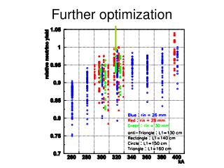
CARIOCA charge sensitivity (pF)-1 vs. CdetAnalytical expression (red line)Some measurements here can not be considered as correct ones A.Kashchuk and O.Levitskaya
ENC updated vs. Cdet M5R4 (WPC), Cdet=245pF Noise Signal Q [e] Th Indication that thermal noise of CARIOCA dominates WR_CARIOCA negative: ENC=2240e+42e/pF BS__CARIOCA negative: ENC=800e+47.2e/pF New From Th to GG 5p.e. at GG=118694 per gap A.Kashchuk and O.Levitskaya
ENC updated vs. Cdet M5R3 (CPC, SCRO), Cdet=141pF Noise Signal Q [e] Th Indication that thermal noise of CARIOCA dominates BS__CARIOCA positive: ENC=300e+53.7e/pF WR_CARIOCA positive: ENC=1800e+45e/pF New From Th to GG 6p.e. at GG=125947 per gap A.Kashchuk and O.Levitskaya
Gas gain needed depends on fraction of charge collected during Tpeakand threshold in p.e. at given threshold in fC (e) For each e.i.-cluster neglecting electron component J.A.Hornbeck, Phys.Rev. 84(1951), 615-620 A.Kashchuk and O.Levitskaya
Table as a new guideline From ENC & Thresholdto GG & HV with corrections of Cdet, S, ENC, Th(p.e.), δ=6%, Diethorn’s: Emin=40±2kV/cm, ΔV=42±1V Taking into account more realistic ENC vs. Cdet presented by BS in November 2009 CARIOCA_positive 300e+53.7e/pF CARIOCA_negative 800e+47.2e/pF Assuming also correct offset in threshold formula found by proper centering A.Kashchuk and O.Levitskaya
The 2-nd task – fix the problem of noisy channels (partial instability) A.Kashchuk and O.Levitskaya
From BS presentation in Oct 2009 Typical instability (!) A.Kashchuk and O.Levitskaya
Important to be mentionedThreshold-scan raw data exist Threshold to be set found However, stable operation is not achieved even at the highest possible threshold, 50fC-----------------------------------------------------------------------------------During Th-scan all channels disabled and only one scanAt Th-setting all channels enabledIt seems at that moment, increased EM-field near the chamber triggers instability A.Kashchuk and O.Levitskaya
A partial positive feed-backwhich is characterized by two superimposed lines,as shown below, has been found in most so called ‘noisy channels’ A.Kashchuk and O.Levitskaya
Vertex frequency helps to see details In general case the vertex frequency depends on spectral density w(t) For white (thermal and shot) noise w(t)=const and cancelled What one can see in addition from Th-scan raw data ? < 60MHz Reminder for any realistic w(f) Log (rate) Infinite with resonance (!) Can trigger instability Peak-up Cross-talks Thermal noise (FEE) Mixture of 3 Threshold^2 A.Kashchuk and O.Levitskaya
A partial positive feed-back evidence Noise Noise Rate I O F Reminder At some conditions: B Log (rate) 109.5Hz Instability Std. Vertex 25MHz Safety margin unknown Threshold^2 Threshold A.Kashchuk and O.Levitskaya
Centering techniquefor reconstruction of the noise distribution 25MHz Too much shift Not enough shift Criterion: the best straightness and correct vertex A.Kashchuk and O.Levitskaya
Problematic chambers/channelsM5C17D --- M5R4 FIR# 14Correct threshold scan in ch2 (left) - stable channelCorrect th-scan at some points becomes incorrect in vicinity of zero-threshold in ch14 (right) - instability due to positive feedback 108.4=230MHz unphysical frequency (!) 25MHz 25MHz Increased slope (reduced ENC) wrong offset Correct slope & offset A.Kashchuk and O.Levitskaya
The previous slide (right) at the best fitWrong both offset and vertex frequency are obtained in ch14 at the best fit (R2=0.998) – ch14 unstable even at the highest possible threshold 50fC (220r.u.) Unphysical frequency (!) 109.48=3GHz 25MHz Best straightness gives unphysical vertex, wrong ENC and offset Vicinity of zero-threshold Increased slope and reduced ENC wrong offset A.Kashchuk and O.Levitskaya
M4C30D --- M4R4 PNPI#21 Vertex frequency more or less in physical limits (40-60MHz) 25MHz 25MHz 107.6=40MHz 107.7=50MHz Channels are still stable (!) A.Kashchuk and O.Levitskaya
M4C30D --- M4R4 PNPI#21 (7 similar chambers) 16 channels are unstable for whole FEB0 even at the highest possible threshold 220 r.u. (50fC) 25MHz 25MHz 108.9=750MHz unphysical (!) 108.4=250MHz unphysical (!) Slope increased in vicinity of zero-threshold w.r.t. slide 20 (!) and channels become unstable A.Kashchuk and O.Levitskaya
M4C31A --- M4R4 PNPI#10616 channels are unstable for whole FEB0 (left) and FEB1 (right) even at the highest possible threshold 220 r.u. (50fC) 109.2=1.5GHz unphysical (!) Slope increased in vicinity of zero-threshold w.r.t. slide 20 (!) and channels become unstable A.Kashchuk and O.Levitskaya
M4C31A --- M4R4 PNPI#10616 channels are unstable channels for whole FEB1 even at the highest possible threshold 220 r.u. 25MHz 25MHz 108.7=540MHz unphysical (!) 108.8=690MHz unphysical (!) Slope increased in vicinity of zero-threshold w.r.t. slide 20 (!) and channels become unstable A.Kashchuk and O.Levitskaya
M5C4D --- M5R4 LNF#006Ch9 (left) Ch11 (right) 108.5=320MHz unphysical (!) 107.8=65MHz Slope increased little bit, if compare two channels, • Channel in left - stable Channel in right - unstable A.Kashchuk and O.Levitskaya
M5C23A --- e.g.M5R3 LNF#53 (4 chambers)similar problems M4C17A3 --- M4R2 FER#25 (one chamber)similar problems • M2R2 #11 looks, as simply wrong Th-setting or offset • For M1 station • a chamber installation map not found on Muon web page 27 chambers as pointed out on Commissioning meeting 26 Oct.09 • http://indico.cern.ch/getFile.py/access?contribId=2&resId=1&materialId=slides&confId=71856 A.Kashchuk and O.Levitskaya
Attention R.Nobrega Threshold Scan Analysis; Tool and Results (15/06/2009 Electronic logbook, record 534) http://indico.cern.ch/getFile.py/access?contribId=15&sessionId=0&resId=2&materialId=slides&confId=48958 According to this global Table one can conclude that many channels in the system behave similar to slide 20 (!) Correct parameter must be ranged, as shown Correct (left) and increasedslope in vicinity of zero-threshold (right) As a result, in the 2-nd case the program will calculate reduced both ENC and its derivative A.Kashchuk and O.Levitskaya
What has to be verified first of all? • 1. Perhaps, noisy channels migrate, appear/disappear… • 2. Is improving situation (margin) in problematic chambers, if one re-connects shielding of cables from Faraday Cage to the wall, • moves cables either close to FC or to the wall (minimizing ground loop), • connects more points on chamber to the wall, etc.? • Extremely important (!) • There is some probability that with beam at nominal intensity and • high EM-fields near the chambers much more channels or even the whole system become unstable due to multiple loops and resonances in ground A.Kashchuk and O.Levitskaya
Is HV minimal? The 3-th – HV minimization by time alignment (tuning) within nominal 25ns HV reduction increases Th in p.e. at fixed Th in fC Let’s start at Th=4p.e. and go down with HV Stop-point for finding HVmin has to be defined by time alignment (tuning) Ratio P/T has to be recorded during this procedure Th=5.3 p.e. in average for bi-gap, as shown here, gives nominal Eff=99.7% for quad gap A.Kashchuk and O.Levitskaya
The 4-th – Gas gain stabilization @ op. point near the knee (HVmin) to conserve time tuning forever to keep constant efficiency, minimal cluster-size, minimal cross-talks at running LHCb experiment A.Kashchuk and O.Levitskaya
A few more steps and we optimize system making it fully computerized A.Kashchuk and O.Levitskaya
Happy END 2010 A.Kashchuk and O.Levitskaya