MPLS Tutorial
MPLS Tutorial. Peter Ashwood-Smith Bilel N. Jamoussi petera@nortelnetworks.com jamoussi@nortelnetworks.com. Tutorial Outline. Overview Label Encapsulations Label Distribution Protocols MPLS & ATM Constraint Based Routing with CR-LDP Summary. “Label Substitution” what is it?.

MPLS Tutorial
E N D
Presentation Transcript
MPLS Tutorial Peter Ashwood-SmithBilel N. Jamoussi petera@nortelnetworks.comjamoussi@nortelnetworks.com
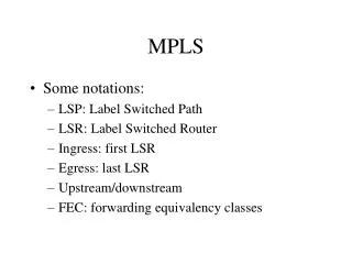
Tutorial Outline • Overview • Label Encapsulations • Label Distribution Protocols • MPLS & ATM • Constraint Based Routing with CR-LDP • Summary
“Label Substitution” what is it? One of the many ways of getting from A to B: • BROADCAST: Go everywhere, stop when you get to B, never ask for directions. • HOP BY HOP ROUTING: Continually ask who’s closer to B go there, repeat … stop when you get to B. “Going to B? You’d better go to X, its on the way”. • SOURCE ROUTING: Ask for a list (that you carry with you) of places to go that eventually lead you to B. “Going to B? Go straight 5 blocks, take the next left, 6 more blocks and take a right at the lights”.
Label Substitution LANE#1 TURN RIGHT USE LANE#2 • Have a friend go to B ahead of you using one of the previous two techniques. At every road they reserve a lane just for you. At ever intersection they post a big sign that says for a given lane which way to turn and what new lane to take. LANE#1 LANE#2
A label by any other name ... There are many examples of label substitution protocols already in existence. • ATM - label is called VPI/VCI and travels with cell. • Frame Relay - label is called a DLCI and travels with frame. • TDM - label is called a timeslot its implied, like a lane. • X25 - a label is an LCN • Proprietary PORS, TAG etc.. • One day perhaps Frequency substitution where label is a light frequency?
SO WHAT IS MPLS ? • Hop-by-hop or source routing to establish labels • Uses label native to the media • Multi level label substitution transport
ROUTE AT EDGE, SWITCH IN CORE IP #L1 IP #L2 IP #L3 IP IP IP Forwarding IP Forwarding LABEL SWITCHING
MPLS: HOW DOES IT WORK UDP-Hello UDP-Hello TCP-open Initialization(s) Label request IP #L2 Label mapping TIME TIME
WHY MPLS ? • Leverage existing ATM hardware • Ultra fast forwarding • IP Traffic Engineering • Constraint-based Routing • Virtual Private Networks • Controllable tunneling mechanism • Voice/Video on IP • Delay variation + QoS constraints
BEST OF BOTH WORLDS IP MPLS+IP ATM CIRCUITSWITCHING PACKETROUTING HYBRID • MPLS + IP form a middle ground that combines the best of IP and the best of circuit switching technologies. • ATM and Frame Relay cannot easily come to the middle so IP has!!
MPLS Terminology • LDP: Label Distribution Protocol • LSP: Label Switched Path • FEC: Forwarding Equivalence Class • LSR: Label Switching Router • LER: Label Edge Router (Useful term not in standards)
Forwarding Equivalence Classes IP1 IP1 IP1 IP2 IP1 IP2 IP2 IP1 #L1 #L3 #L1 #L2 #L2 #L3 IP2 IP2 LSR LSR LER LER LSP Packets are destined for different address prefixes, but can be mapped to common path • FEC = “A subset of packets that are all treated the same way by a router” • The concept of FECs provides for a great deal of flexibility and scalability • In conventional routing, a packet is assigned to a FEC at each hop (i.e. L3 look-up), in MPLS it is only done once at the network ingress
LABEL SWITCHED PATH (vanilla) #14 #311 #216 #99 #311 #963 #311 #963 #14 #612 #462 #311 #99 #5 - A Vanilla LSP is actually part of a tree from every source to that destination (unidirectional). - Vanilla LDP builds that tree using existing IP forwarding tables to route the control messages.
MPLS BUILT ON STANDARD IP 3 47.1 1 2 1 3 2 1 47.2 3 47.3 2 • Destination based forwarding tables as built by OSPF, IS-IS, RIP, etc.
IP FORWARDING USED BY HOP-BY-HOP CONTROL IP 47.1.1.1 47.1 1 IP 47.1.1.1 2 IP 47.1.1.1 1 3 2 IP 47.1.1.1 1 47.2 3 47.3 2
MPLS Label Distribution Request: 47.1 Request: 47.1 Mapping: 0.50 Mapping: 0.40 1 47.1 3 3 2 1 1 2 47.3 3 47.2 2
Label Switched Path (LSP) IP 47.1.1.1 IP 47.1.1.1 1 47.1 3 3 2 1 1 2 47.3 3 47.2 2
EXPLICITLY ROUTED OR ER-LSP Route={A,B,C} #972 #14 #216 #14 #972 #462 B C A - ER-LSP follows route that source chooses. In other words, the control message to establish the LSP (label request) is source routed.
EXPLICITLY ROUTED LSP ER-LSP IP 47.1.1.1 IP 47.1.1.1 1 47.1 3 3 2 1 1 2 47.3 3 47.2 2
ER LSP - advantages • Operator has routing flexibility (policy-based, QoS-based) • Can use routes other than shortest path • Can compute routes based on constraints in exactly the same manner as ATM based on distributed topology database.(traffic engineering)
ER LSP - discord! • Two signaling options proposed in the standards: CR-LDP, RSVP extensions: • CR-LDP = LDP + Explicit Route • RSVP ext = Traditional RSVP + Explicit Route + Scalability Extensions • Not going to be resolved any time soon, market will probably have to resolve it. • Survival of the fittest not such a bad thing.
Tutorial Outline • Overview • Label Encapsulations • Label Distribution Protocols • MPLS & ATM • Constraint Based Routing with CR-LDP • Summary
Label Encapsulation ATM FR Ethernet PPP L2 VPI VCI DLCI “Shim Label” Label “Shim Label” ……. IP | PAYLOAD MPLS Encapsulation is specified over various media types. Top labels may use existing format, lower label(s) use a new “shim” label format.
MPLS Link Layers • MPLS is intended to run over multiple link layers • Specifications for the following link layers currently exist: • ATM: label contained in VCI/VPI field of ATM header • Frame Relay: label contained in DLCI field in FR header • PPP/LAN: uses ‘shim’ header inserted between L2 and L3 headers • Translation between link layers types must be supported MPLS intended to be “multi-protocol” below as well as above
MPLS Encapsulation - ATM ATM LSR constrained by the cell format imposed by existing ATM standards 5 Octets ATM Header Format VPI VCI PT HEC CLP Label Option 1 Label Combined Label Option 2 Option 3 ATM VPI (Tunnel) Label AAL 5 PDU Frame (nx48 bytes) ••• n 1 Network Layer Header and Packet (eg. IP) Generic Label Encap. (PPP/LAN format) AAL5 Trailer ATM SAR 48 Bytes 48 Bytes ATM Header • • • ATM Payload • Top 1 or 2 labels are contained in the VPI/VCI fields of ATM header • - one in each or single label in combined field, negotiated by LDP • Further fields in stack are encoded with ‘shim’ header in PPP/LAN format • - must be at least one, with bottom label distinguished with ‘explicit NULL’ • TTL is carried in top label in stack, as a proxy for ATM header (that lacks TTL)
MPLS Encapsulation - Frame Relay Generic Encap. (PPP/LAN Format) Q.922 Header Layer 3 Header and Packet ••• n 1 C/ R FE CN E A BE CN D E E A DLCI Size = 10, 17, 23 Bits DLCI DLCI • Current label value carried in DLCI field of Frame Relay header • Can use either 2 or 4 octet Q.922 Address (10, 17, 23 bytes) • Generic encapsulation contains n labels for stack of depth n • - top label contains TTL (which FR header lacks), ‘explicit NULL’ label value
MPLS Encapsulation - PPP & LAN Data Links MPLS ‘Shim’ Headers (1-n) ••• n 1 Network Layer Header and Packet (eg. IP) Layer 2 Header (eg. PPP, 802.3) 4 Octets Label Stack Entry Format TTL Label Exp. S Label: Label Value, 20 bits (0-16 reserved) Exp.: Experimental, 3 bits (was Class of Service) S: Bottom of Stack, 1 bit (1 = last entry in label stack) TTL: Time to Live, 8 bits • Network layer must be inferable from value of bottom label of the stack • TTL must be set to the value of the IP TTL field when packet is first labelled • When last label is popped off stack, MPLS TTL to be copied to IP TTL field • Pushing multiple labels may cause length of frame to exceed layer-2 MTU • - LSR must support “Max. IP Datagram Size for Labelling” parameter • - any unlabelled datagram greater in size than this parameter is to be fragmented MPLS on PPP links and LANs uses ‘Shim’ Header Inserted Between Layer 2 and Layer 3 Headers
Tutorial Outline • Overview • Label Encapsulations • Label Distribution Protocols • MPLS & ATM • IETF Status • Nortel’s Activity • Summary
Label Distribution Protocols • Overview of Hop-by-hop & Explicit • Label Distribution Protocol (LDP) • Constraint-based Routing LDP (CR-LDP) • Extensions to RSVP • Extensions to BGP
Comparison - Hop-by-Hop vs. Explicit Routing Hop-by-Hop Routing Explicit Routing • Distributes routing of control traffic • Builds a set of trees either fragment by fragment like a random fill, or backwards, or forwards in organized manner. • Reroute on failure impacted by convergence time of routing protocol • Existing routing protocols are destination prefix based • Difficult to perform traffic engineering, QoS-based routing • Source routing of control traffic • Builds a path from source to dest • Requires manual provisioning, or automated creation mechanisms. • LSPs can be ranked so some reroute very quickly and/or backup paths may be pre-provisioned for rapid restoration • Operator has routing flexibility (policy-based, QoS-based, • Adapts well to traffic engineering Explicit routing shows great promise for traffic engineering
Explicit Routing - MPLS vs. Traditional Routing • Connectionless nature of IP implies that routing is based on information in each packet header • Source routing is possible, but path must be contained in each IP header • Lengthy paths increase size of IP header, make it variable size, increase overhead • Some gigabit routers require ‘slow path’ option-based routing of IP packets • Source routing has not been widely adopted in IP and is seen as impractical • Some network operators may filter source routed packets for security reasons • MPLS’s enables the use of source routing by its connection-oriented capabilities • - paths can be explicitly set up through the network • - the ‘label’ can now represent the explicitly routed path • Loose and strict source routing can be supported MPLS makes the use of source routing in the Internet practical
Label Distribution Protocols • Overview of Hop-by-hop & Explicit • Label Distribution Protocol (LDP) • Constraint-based Routing LDP (CR-LDP) • Extensions to RSVP • Extensions to BGP
Label Distribution Protocol (LDP) - Purpose Label distribution ensures that adjacent routers have a common view of FEC <-> label bindings Routing Table: Addr-prefix Next Hop 47.0.0.0/8 LSR3 Routing Table: Addr-prefix Next Hop 47.0.0.0/8 LSR2 LSR1 LSR3 LSR2 IP Packet 47.80.55.3 Label Information Base: Label-In FEC Label-Out XX 47.0.0.0/8 17 For 47.0.0.0/8 use label ‘17’ Label Information Base: Label-In FEC Label-Out 17 47.0.0.0/8 XX Step 2: LSR communicates binding to adjacent LSR Step 3: LSR inserts label value into forwarding base Step 1: LSR creates binding between FEC and label value Common understanding of which FEC the label is referring to! Label distribution can either piggyback on top of an existing routing protocol, or a dedicated label distribution protocol (LDP) can be created
Label Distribution - Methods Label Distribution can take place using one of two possible methods Downstream Label Distribution Downstream-on-Demand Label Distribution LSR2 LSR1 LSR2 LSR1 Label-FEC Binding Request for Binding • LSR2 and LSR1 are said to have an “LDP adjacency” (LSR2 being the downstream LSR) • LSR2 discovers a ‘next hop’ for a particular FEC • LSR2 generates a label for the FEC and communicates the binding to LSR1 • LSR1 inserts the binding into its forwarding tables • If LSR2 is the next hop for the FEC, LSR1 can use that label knowing that its meaning is understood Label-FEC Binding • LSR1 recognizes LSR2 as its next-hop for an FEC • A request is made to LSR2 for a binding between the FEC and a label • If LSR2 recognizes the FEC and has a next hop for it, it creates a binding and replies to LSR1 • Both LSRs then have a common understanding Both methods are supported, even in the same network at the same time For any single adjacency, LDP negotiation must agree on a common method
DOWNSTREAM MODE MAKING SPF TREE COPY IN H/W #14 #311 #216 #99 #311 #963 #311 D #963 #14 #612 D #462 D D D #311 #99 #5 D D D
DOWNSTREAM ON DEMAND MAKING SPF TREE COPY IN H/W #14 #311 #216 #99 #311 #963 #311 D D? D? #963 #14 D? D? #612 D D? #462 D D? D D #311 #99 #5 D D D D? D?
Distribution Control: Ordered v. Independent Next Hop (for FEC) MPLS path forms as associations are made between FEC next-hops and incoming and outgoing labels Incoming Label Outgoing Label Independent LSP Control Ordered LSP Control • Label-FEC binding is communicated to peers if: • - LSR is the ‘egress’ LSR to particular FEC • - label binding has been received from upstream LSR • LSP formation ‘flows’ from egress to ingress • Each LSR makes independent decision on when to generate labels and communicate them to upstream peers • Communicate label-FEC binding to peers once next-hop has been recognized • LSP is formed as incoming and outgoing labels are spliced together Definition • Labels can be exchanged with less delay • Does not depend on availability of egress node • Granularity may not be consistent across the nodes at the start • May require separate loop detection/mitigation method • Requires more delay before packets can be forwarded along the LSP • Depends on availability of egress node • Mechanism for consistent granularity and freedom from loops • Used for explicit routing and multicast Comparison Both methods are supported in the standard and can be fully interoperable
INDEPENDENT MODE #14 #311 #216 #99 #311 #963 #311 D #963 #14 #612 D #462 D D D #311 #99 #5 D D D
Label Retention Methods Binding for LSR5 LSR2 An LSR may receive label bindings from multiple LSRs Some bindings may come from LSRs that are not the valid next-hop for that FEC LSR1 LSR5 Binding for LSR5 LSR3 Binding for LSR5 LSR4 Conservative Label Retention Liberal Label Retention LSR2 LSR2 Label Bindings for LSR5 Label Bindings for LSR5 LSR1 LSR1 LSR3 LSR3 LSR4’s Label LSR3’s Label LSR2’s Label LSR4’s Label LSR3’s Label LSR2’s Label LSR4 LSR4 Valid Next Hop Valid Next Hop • LSR maintains bindings received from LSRs other than the valid next hop • If the next-hop changes, it may begin using these bindings immediately • May allow more rapid adaptation to routing changes • Requires an LSR to maintain many more labels • LSR only maintains bindings received from valid next hop • If the next-hop changes, binding must be requested from new next hop • Restricts adaptation to changes in routing • Fewer labels must be maintained by LSR Label Retention method trades off between label capacity and speed of adaptation to routing changes
LIBERAL RETENTION MODE These labels are kept incase they are needed after a failure. #216 D D #963 #14 #622 #612 D #462 D D D D #311 #422 #99 #5 D D D
CONSERVATIVE RETENTION MODE These labels are released the moment they are received. #216 D D #963 #14 #622 #612 D #462 D D D D #311 #422 #99 #5 D D D
LDP - STATUS • Gone to last call • Multi Vendor interoperability demonstrated for DSOD on OC-3/ATM by (Nortel Networks & Cisco) at Interop/99 • Source code for these PDUs publicly available: www.NortelNetworks.com/mpls
Label Distribution Protocols • Overview of Hop-by-hop & Explicit • Label Distribution Protocol (LDP) • Constraint-based Routing LDP (CR-LDP) • Extensions to RSVP
Constraint-based LSP Setup using LDP • Uses LDP Messages (request, map, notify) • Shares TCP/IP connection with LDP • Can coexist with vanilla LDP and inter-work with it, or can exist as an entity on its own • Introduces additional data to the vanilla LDP messages to signal ER, and other “Constraints”
ER-LSP Setup using CR-LDP 2. Request message processed and next node determined. Path list modified to <C,D> 3. Request message terminates. 1. Label Request message. It contains ER path < B,C,D> 6. When LER A receives label mapping, the ER established. 5. LSR C receives label to use for sending data to LER D. Label table updated 4. Label mapping message originates. LER A LSR B LSR C LER D ER Label Switched Path Ingress Egress
LDP/CR-LDP INTERWORKING INSERT ER{A,B,C} #216 #99 #311 #14 #612 #462 #5 A B C LDP CR-LDP - It is possible to take a vanilla LDP label request let it flow vanilla to the edge of the core, insert an ER hop list at the core boundary at which point it is CR-LDP to the far side of the core.
Basic LDP Message additions • LSPID: A unique tunnel identifier within an MPLS network. • ER: An explicit route, normally a list of IPV4 addresses to follow (source route) the label request message. • Resource Class (Color): to constrain the route to only links of this Color. Basically a 32 bit mask used for constraint based computations. • Traffic Parameters: similar to ATM call setup, which specify treatment and reserve resources.
CRLSP characteristics not edge functions • The approach is like diff-serv’s separation of PHB from Edge • The parameters describe the “path behavior” of the CRLSP, i.e. the CRLSP’s characteristics • Dropping behavior is not signaled • Dropping may be controlled by DS packet markings • CRLSP characteristics may be combined with edge functions (which are undefined in CRLDP) to create services • Edge functions can perform packet marking • Example services are in an appendix
Peak rate • The maximum rate at which traffic should be sent to the CRLSP • Defined by a token bucket with parameters • Peak data rate (PDR) • Peak burst size (PBS) • Useful for resource allocation • If a network uses the peak rate for resource allocation then its edge function should regulate the peak rate • May be unused by setting PDR or PBS or both to positive infinity