BWR Vent Order Implementation Workshop II
BWR Vent Order Implementation Workshop II. April 9 -10, 2014 Baltimore. Workshop Purpose and Plan. Phase 1 (wet well) template for Overall Implementation Plans for NRC Order EA-13-109.

BWR Vent Order Implementation Workshop II
E N D
Presentation Transcript
BWR Vent Order Implementation Workshop II April 9 -10, 2014 Baltimore
Workshop Purpose and Plan • Phase 1 (wet well) template for Overall Implementation Plans for NRC Order EA-13-109. • Review order requirements and accepted approach to complying with Phase 1 of the Order being developed in conjunction with the NRC. • Focus on the detailed physical and analytic elements of implementation.
BWR Mark I/II Severe Accident Vent OrderKey Dates • Order issued June 6, 2013; two phases • Severe accident wetwell vent by June 30, 2018 • Severe accident drywell vent by June 30, 2019 • Option to demonstrate drywell vent not needed • Guidance NEI 13-02 R.0 and JLD-ISG-2013-02 R.0 • Phase 1 (WW) Guidance issued November 2013 • Developing template for Overall Integrated Plan for meeting Order. • BWROG developing engineering guidance for vent. • Phase 2 (DW) Guidance by April 2015
Venting and Filtering StrategiesBWR Mark I and II • Prevent core damage during SBO/ELAP • Venting via hardened wetwell vent • Water injection via FLEX • Following core damage during SBO/ELAP, prevent containment failure • Venting via hardened wetwell and/or drywell vent • Water injection via “beyond FLEX” • Filtering releases via containment water injection and pressure control
Phase 1 Activities Timeline Post OIP Template Development • June 2014 • July – Aug 2014 • Oct 2014 • Dec 2014 • Dec 2014 – Phase 1 OIP due – Develop 6-month status template – Phase 1 pilot plant ISE issued – All Phase 1 plant ISE issued – 1st 6-month status due
Estimated Phase 2 Guidance Timeline Mar 2014 – NEI Working Group define goals and approach for Phase 2 Apr – May 2014 – NEI WG draft 13-02 Phase 2 scope from Industry perspective Jun – Sep 2014 – NRC/NEI Draft 13-02 Phase 2 scope Oct 2014 – NEI/BWROG Industry Comment and Feedback Nov 2014 – NEI Phase 2 Draft Revision Provided to NRC for reference in ISG Dec 2014 – NRC publish draft ISG for public comment Feb 2015 – NRC Public comment period closed Mar 2015 – NRC Issues approved ISG Mar 2015 – NEI/NRC Workshop on Phase 2 Apr – May 2015 – NRC/NEI OIP Template structure and content without Pilots May – Jul 2015 – NRC/NEI OIP Template Pilots including Option for No DW Vent Pilot Aug 2015 – NEI/BWROG Draft OIP To Industry for Comment for Workshop Sep 2015 – NEI/NRC OIP Workshop on Pilots and Template use Oct 2015 – NEI OIP finalized and included in a revision to 13-02 Dec 2015 – Stations OIP due to NRC
Industry Documents • Template timeline • FAQ & White Paper Process • Selected Template Elements • Generic • Plant Hatch Pilot • Nine Mile Point 2 Pilot
Template Development Information and Key Dates • Template Development • Pilot plant(s) identified – Hatch as MK I & NMP2 as MK II • Draft template by January 20, 2014 – Presented on Jan 15 • Final Draft template March 15, 2014 – After Pilots • NEI 13-02 Revision for OIP template and FAQs by April 21, 2014 • NRC-NEI Joint Template Meetings • January 15, 2014 – Complete (Draft Template & 3 FAQ) • January 29, 2014 – (Template Elements & FAQs) • February 19, 2014 (Pilot Plant Hatch, FAQs & White Papers) • March 5, 2014 (NMP2 Pilot Differences, FAQ & White Paper) • March 26, 2014 (NRC Feedback on OIP Pilots/Workshop Prep) • Industry Template Workshop, April 9-10 in Baltimore • NRC-NEI Check-up Conference Call Proposed for May 7
Frequently Asked Questions • Clarification items brought to industry NEI 13-02 core team • NEI 13-02 Core Team to provide consensus response • Select FAQs presented to the NRC staff in draft version (interpretation FAQs) • Final FAQ documented on NEI website • Clarification items larger than FAQ will be resolved via other means of NEI 13-02 revision or white paper endorsement • Phase 2 revision of NEI 13-02 will incorporate appropriate FAQs or white papers
Frequently Asked Questions FAQ HCVS-01, 02, 03, 04, 05, 06, 07 and 08 have been submitted for NRC Concurrence
White Paper Topics • HCVS-WP-01: HCVS Dedicated Motive Force • Scope of operator actions for selected HCVS electrical and pneumatic supplies • HCVS-WP-02: HCVS Cyclic Operations Approach • Accident sequence • Number of vent cycles • Radiological limitations from HCVS operation • HCVS-WP-03: Hydrogen/CO Control Measures • Passive measures • Active measures • HCVS-WP-04: FLEX/HCVS Interactions • Portable equipment use under severe accident and BDBEE conditions
Template Elements Template Goals: • Use Hybrid 050/049 Template with Order and ISG (NEI 13-02) Cross Reference • Directly align to the ISG • Describe the phased approach to implementation • Big picture schedule statement • Wetwell performance objectives • Discuss the section 1.1 objectives of attachment 2 in order • Discuss the requirements in sections 4.1, 4.2 and 6.1 and appendix's F and G of NEI 13-02 • Drywell performance objectives • Quality standards • Programmatic requirements • Linkage to ISE or SE
Template Elements Proposed Template with Order and ISG (NEI 13-02) Cross Reference: Introduction Part 1: General Integrated Plan Elements and Assumptions Part 2: Boundary Conditions for WW Vent with specifics about the compliance actions relative to the ISG and NEI 13-02 section 2 Part 3: Boundary Conditions for DW Vent with specifics about the compliance actions relative to the ISG and NEI 13-02 section 3 Part 4: Programmatic Controls, Training, Drills and Maintenance Elements Part 5: Milestone table elements Attachment 1: Portable Equipment Attachment 2: Sequence of Events Timeline Attachment 3: Conceptual Sketches Attachment 4: Failure Evaluation Table Attachment 5: References Attachment 6: Changes/Updates to this OIP Attachment 7: Open Items in HCVS OIP
Template Elements Part 1: General Integrated Plan Elements and Assumptions • Key Site assumptions to implement NEI 13-02 strategies • Grouping of Assumptions as FLEX, Generic and Site Specific. • Considering making an FAQ on FLEX assumptions and one on Generic to use as a reference in the template.
Template Elements Part 2: Boundary Conditions for WW Vent with specifics about the compliance actions relative to the ISG and NEI 13-02 section 2 • Severe Accident • First 24 • Beyond 24 hours • Support Equipment Functions • BDBEE Venting • Severe Accident Venting
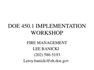
Template Elements Part 4: Programmatic Controls, Training, Drills and Maintenance Elements Part 5: Milestone table elements Attachments • Attachment 1: Portable Equipment • Attachment 2: Sequence of Events Timeline • Operator action constraints timeline is determined based on the following sequences: • Sequence 1 is a FLEX run with Venting in a BDBEE without core damage. • Sequence 2 is based on SECY-12-0157 results for a prolonged SBO (ELAP) with the delayed loss of RCIC • Sequence 3 is based on SOARCA results for an SBO (ELAP) with failure of RCIC to inject.
Representative BWR Venting Timelines Anticipatory Venting RCIC starts SBO Case 1 Ref: Plant t=0s t ≈.5 m t ≈ 5 hrs t ≈ 18 hrs Containment Venting (anticipatory venting not represented in SECY-12-0157) No Injection No Injection Portable generator providing power to Safety Related 480VAC System (Ref Plant OIP) Level at TAF Case 2 Ref: SECY-12-0157 Core Damage Core Damage Vessel Breach Vessel Breach t ≈ 23 hrs t ≈ 24 hrs t ≈ 34 hrs Containment Venting (based on exceeding PCPL) Case 3 Ref: SOARCA t ≈ 1 hr t≈ 8 hr Legend References: Case 1: Reference Plant FLEX Overall Integrated Plan Case 2: SECY-12-0157 – ML12344A030 Case 3: SOARCA – ML13150A053 Adequate core cooling maintained Injection Lost Increased shine and leakage of radionuclides primarily from Wetwell HCVS Post Core Damage Dose Evaluation Required Not to scale
Review of Key Elements of Phase 1 Overall Integrated Plan Template
Hatch SA HCVS Pilot Template Elements Review of Plant Hatch completion of items in revision C3 of the Severe Accident HCVS OIP Template
Nine Mile Point Unit 2SA HCVS Pilot Template Major Differences Review of Nine Mile Point Unit 2 Major Differences from Mark I pilot for Severe Accident HCVS OIP Template
Hatch OIP Major Elements • Adding Site Characteristics important to HCVS • Control Building and Rx Building Layout • Main Stack and vent pipe locations • Time and Environmental Constraint Items • Rupture disc • HCVS Operation • Battery power actions • >24 Hour motive force
NMP2 OIP Site Characteristics Important to HCVS • The primary location for HCVS operation will be the Main Control Room • The alternate location for HCVS operation will be the Reactor Building track bay, northeast side of Reactor Building, ground elevation • The HCVS release point will be at least 3 feet above the top of the Reactor Building on the northwest side of the Reactor Building
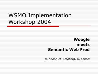
Hatch HCVS Venting Timelines t ≈.5 m RCIC starts t = 1 hr ELAP Declared t=0s SBO Case 1 FLEX Successful Ref: HNP FLEX OIP t ≈ 18 hrs Containment Venting (anticipatory venting not represented in SECY-12-0157) t ≈ 7 hrs Anticipatory Venting Blow rupture disc No Injection No Injection t ≈ 10 hrs Portable generator in place for FLEX and HCVS loads. Level at TAF Case 2 RCIC Late Failure Ref: SECY-12-0157 t ≈ 23 hrs t ≈ 24 hrs t ≈ 34 hrs Core Damage Core Damage Vessel Breach Vessel Breach t ≈ 11 hrs Begin monitoring at MCR or ROP HCVS pneumatic and battery status. No replenishment expected to be required before t = 24 hours Containment Venting (based on preventing exceeding PCPL) t ≈ 24 hrs Replenishment of HCVS power and pneumatic supplies Level at TAF t ≈ 12 hrs Transfer to HCVS Battery Case 3 RCIC Early Failure Ref: SOARCA t ≈ 2 hr t ≈ 1 hr t ≈ 11 hrs t≈ 8 hrs t ≈ 24 hrs t ≈ 12 hrs References: Case 1: HNP FLEX Overall Integrated Plan Case 2: SECY-12-0157 – ML12344A030 Case 3: SOARCA – ML13150A053 Legend Adequate core cooling maintained Injection Lost Increased shine and leakage of radionuclides primarily from Wetwell HCVS Post Core Damage Dose Evaluation Required HCVS Time evaluation required Not to scale
Hatch OIP Major Elements • 7.3 Hours, Initiate use of Hardened Containment Vent System (HCVS) per site procedures to maintain containment parameters below design limits and within the limits that allow continued use of RCIC for mitigation in a BDBEE - HCVS controls and instruments associated with containment will be DC powered and operated from the MCR or a Remote Operating Station on each unit. Thus initiation of the HCVS from the MCR or the Remote Operating Station within 7.3 hours is acceptable because the actions can be performed any time after declaration of an ELAP (1 hour) until the venting is needed. In the event of Severe Accident HCVS initiation all required actions occur at a time further removed from an ELAP declaration than the BDBEE HCVS timeline as shown in Attachment 2.
NMP2 OIP Differences Time and Environment Constraint Items • 2 Hours, Initiate use of Hardened Containment Vent System (HCVS) per site procedures to maintain containment parameters within the limits that allow continued use of RCIC. Initiation of the HCVS can be completed with manipulation of only 4 switches located within the MCR. The reliable operation of HCVS will be met because HCVS meets the seismic requirements identified in NEI 13-02 and will be powered by dedicated HCVS batteries with motive force supplied to HCVS valves from installed nitrogen storage bottles. HCVS controls and HCVS instrumentation will be provided from a dedicated panel in the MCR. Other containment parameter instrumentation associated with operation of the HCVS is available in the MCR. Operation of the system will be available from either the MCR or a ROS. Dedicated HCVS batteries will provide power for greater than 24 hours. Therefore, initiation of the HCVS from the MCR or the ROS within 2 hours is acceptable because of the simplicity and limited number of operator actions. Placing the HCVS in operation to maintain containment parameters within design limits for either BDBEE or SA venting would occur at a time further removed from ELAP declaration as shown on the sequence of events timeline on the previous slide
Hatch OIP Major Elements • At >24 Hours, portable diesel generators will be installed and connected to the pigtail of the battery chargers to supply power to HCVS components/instruments; time critical at a time greater than 25 hours. Current battery durations are calculated to last greater than 26 hours. The connections, location of the DG and access for refueling will be located in an area that is accessible to operators in the Control Building or in the yard area because the HCVS vent pipe is underground once it leaves the Reactor Building. [OPEN ITEM 3: Evaluate location of Portable DG for accessibility under Severe Accident HCVS use]
NMP2 OIP Differences Time and Environment Constraint Items (Cont’d) • 24 Hours, Replace/install additional nitrogen bottles or install compressor. The nitrogen station will have extra connections so that new bottles can be added or an air compressor can be connected while existing bottles supply the HCVS. This can be performed at any time prior to 24 hours to ensure adequate capacity is maintained so this time constraint is not limiting
NMP2 OIP Differences Time and Environment Constraint Items (Cont’d) • 24 Hours, connect back-up power to HCVS battery charger. The HCVS batteries are calculated to last a minimum of 24 hours. The HCVS battery charger will be able to be re-powered either from the 600 VAC bus that will be re-powered from a portable diesel generator (DG) put in place for FLEX or locally (Reactor Building Track Bay) from a small portable generator • The DG will be staged and placed in service within 8 hours (Reference FLEX OIP) and therefore will be available prior to being required. In the event that the DG is not available, a local connection will allow a small portable generator to be connected to the UPS to provide power
Hatch OIP Major Elements • Vent characteristics • Boundary valve use and cross flow • Remote operating station use • FLEX type actions • Electric power details • Milestone schedule
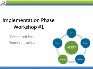
NMP2 OIP Differences Drywell piping and valve configuration shown for completeness, not for Phase 1 compliance
NMP2 OIP Differences Equipment Usage • NMP2 will utilize a mixed system, sharing the following components • Containment penetrations • Inboard and Outboard PCIVs • Piping to HCVS vent tee • Boundary with interfacing systems limited to • 20” AOV to Standby Gas Treatment System (GTS) • 2” SOV bypass around 20” AOV to GTS
NMP2 OIP Differences GDC-56 Exemption • The inboard primary containment isolation valves (PCIV) to be shared with the HCVS system are located inside the primary containment • Most plants implemented a GDC-56 exemption as part of the plant design basis for an alternate configuration • The inboard PCIV will be located outside the containment and thereby significantly improve the reliability of the HCVS system
NMP2 OIP Differences Discharge Point • NMP2 will utilize a release point above the Reactor Building roof independent of the metrological stack • Follows criteria per FAQ HCVS-04
NMP2 OIP Differences Power Supply • NMP2 HCVS system will be powered by the Divisional Class 1E 600 volt power through a transformer and 125 volt battery charger during normal operation • On loss of AC power, a battery capable of supplying HCVS loads for at least 24 hours will supply HCVS loads without Operator action • A FLEX portable diesel will be connected to repower the 600 volt power within 8 hours to repower the HCVS battery charger • A small portable 120/240 volt generator provides a backup to the FLEX diesel generator that will provide HCVS loads and battery charger through a manual transfer switch • Station batteries will not be utilized for HCVS loads
NMP2 OIP Differences Containment Protection Features • Inadvertent actuation protection is provided by keylock switches used to power up the HCVS panel • Additional keylock switches will be utilized for control of the shared HCVS/Primary Containment Isolation Valves (PCIVs) • The HCVS valve double solenoid valve arrangement eliminates the need for defeating containment isolation signals using electrical jumpers or lifted leads • There are no rupture discs in the NMP2 HCVS design
NMP2 OIP Differences Remote Manual Mechanisms • Manual valves in the pneumatic supply lines will provide alternate means for HCVS valve operation • Electrical power is not required for this method • A manual override for HCVS valve solenoids is being considered • A handwheel for the PCV is being considered, but will not be credited due to environmental concerns in proximity to the valve
Hatch OIP Major Elements • Portable equipment use • Without core damage • With core damage • Example Drawings • Electrical • Mechanical • Plant Layout
NMP2 OIP Differences Drywell piping and valve configuration shown for completeness, not for Phase 1 compliance
BWROG Companion Guideline for NEI 13-02Progress between Workshops Pat Fallon - DTE Dennis Henneke - GEH BWR Vent Order Implementation Workshop II 4/9/14 • Baltimore, MD
Introduction • The BWROG Implementation Guidelines supporting NEI 13-02 (referred to as the Companion Document) is developed to: • Provide guidance on “how to” meet the “what” requirements in NEI 13-02 and NRC Order EA-13-109. • Include discussion previously removed from 13-02, due to level of detail (e.g. Hydrogen Overpressure).
BWROG Companion Document • Beginnings: • Started as discussion point during formulation of NEI-13-02 • NEI-13-02 was created to work with EA-13-109 to fully define acceptable equipment and man-machine interface to make a successful Severe Accident Capable Hardened Vent. • NEI-13-02 did NOT contain any “how to” elements for implementation. • NEI-13-02 was endorsed (largely) by the NRC due to multiple interface sessions with a small industry team and NEI. • NEI-13-02 needed to have additional industry input to create a workable method for HCVS implementation that would allow use of work conducted for EA-12-050 and still meet the intents of NEI-13-02.
BWROG Companion Document • Thanks to the Authors: • Pat Fallon - DTE • Shayne Tenace - Exelon • Bob Cowen - GEH • David Burch - Entergy • Deep Ghosh - SNC • Bob Ginsberg – Duke Energy • Frank Loscalzo - TVA • Dennis Henneke - GEH • Scott Wood - Energy NW • Harold Trenka - Exelon • Phil Amway - Exelon • Keith Ward – Duke Energy • Glen Seeman – GEH • Rich Centenaro - PPL Also THANKS to the large group of reviewers and commenters.
BWROG Companion Document • First Pass • Introduced the concept at first HCVS Workshop in Baltimore 11-13-2013. • Slides showed more of a wish list than any concrete method of creation of “how to” elements. • A few Items were not developed (Appendix J on Reliable Operator Actions) • A few new items were added (e.g. interface with FLEX) • Example slide on Section 5.0 follows.