CALICE Project Update: Electronics Status, Remaining Prototype Tests, ECAL Schedule, HCAL Schedule, CERC Status, DAC Int
This update provides information on the CALICE project, including the electronics status, remaining prototype tests, ECAL and HCAL schedules, CERC status, DAC internal loopback path, and strontium source tests.

CALICE Project Update: Electronics Status, Remaining Prototype Tests, ECAL Schedule, HCAL Schedule, CERC Status, DAC Int
E N D
Presentation Transcript
CALICE(-UK) Status Paul Dauncey Paul Dauncey
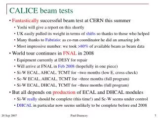
News • FY03/04 final (I think) spend: travel £11.9k, equipment £59.1k • FY04/05 travel budget £68k • Unlikely to be big beam test in this FY • No equipment funds; needs to be sorted out as still have ~£50k to spend • LCWS04 at Paris last week • UK well represented; 6 UK talks • CALICE ECAL around a year ahead of US Si-W effort • Next EFCA LC meeting in Durham in Sep • Should try to have big UK turnout Paul Dauncey
Electronics status • Spent much of Apr at Ecole Polytechnique testing our prototype boards • Internal tests of boards look very good • VFE tests mainly very successful • Single silicon wafer; saw strontium peak and cosmic peak • Have calibrated our system against a real MIP peak • Some plots from my LCWS04 talk follow • Issues • One (of the two) prototypes is effectively unusable; it does not always boot and even if it does, it doesn’t always stay up • The trigger latency is very close to the maximum ~200ns; too close for comfort so needs to be shortened Paul Dauncey
Remaining prototype tests • Need to redo tests with “final” VFE PCB, V3 (currently V2) • Available mid to late May, three PCBs will be fully equipped with wafers • Will aim for three-layer cosmic test setup to see tracks • Need to understand problems with bad board • 50% yield will not be good enough! • Need to test with AHCAL VFE-equivalent PCB • Highly likely to use SiPM into (modified?) VFE chip • Straightforward match to our readout boards • PCB available in Jun/Jul • Need to verify the rest of our board • Large chunk of board (the “back-end”) completely untested • No firmware for any of this verification has been provided yet • No apparent progress either; this is THE major issue now • There is no contingency for engineering effort Paul Dauncey
ECAL schedule • Assembly paced by VFE PCB production • Can proceed to fabrication after verification of V3 in May • 60 boards needed, fabricated by Jul • First 10 layers assembled by Sep • We go back to Paris to test these 10 layers in Sep • 10 layer cosmic tracker at Ecole Polytechnique • Pushing to go to DESY test beam asap, even if only 10 layers at first • Maybe start with beam in Oct/Nov with 10 layers, complete by Dec/Jan • 10 layers needs two readout boards • Could use prototypes if necessary, but need more when >10 layers anyway • Aim to finish UK board production in time for Sep cosmic tests • Complete tests and firmware by end Jun • Redesign and relayout (?) by end Jul • Fabrication and assembly by end Aug Paul Dauncey
HCAL schedule • AHCAL schedule less well defined • No VFE-equivalent design yet but aiming for prototype board in Jun • Assembly paced mainly by scintillating tile/fibre production • Original test beam ready date of spring 2005 has slipped to summer 2005 • DHCAL schedule even less well defined • No VFE electronics prototype yet; ASIC design underway but could require several iterations • Funding unclear; RPCs are cheap but 400k channels of electronics (even digital) is not • Original test beam ready date of summer 2005 has slipped to end 2005 • There is a CALICE presentation at the DESY PRC on May 27 • I have requested a SB/TB meeting the day before • Nail down the various schedules; we cannot keep slipping continuously • Make a decision on the test beam location; essential for the PPRP (IMPO) • Have practise talk session for PRC presentations Paul Dauncey
CERC status • Prototype design completed last summer • Two prototype boards fabricated in November • Currently under tests with a prototype VFE-PCB in Ecole Polytechnique • Further tests with final version of VFE-PCB in May • CERC final production in July/Aug Paul Dauncey
DAC internal loopback path • ADC has two inputs per channel; selected in configuration • DAC feeds directly into one; “internal” loopback • Differential analogue path only ~1cm and entirely tracked on PCB • Expect minimal noise • Scan DAC and check linearity of ADC response • Intrinsic CERC performance, not due to external electronics, etc. Paul Dauncey
DAC internal loopback tests • Plot ADC vs DAC setting • Good linearity over most of the range • DAC saturation seen in lowest 1% of range (not due to ADC!) • Mismatch of DAC range to ADC; only covers ¼ of ADC range (0 to ~15k for ADC range of ±32k) ADC ADC DAC RMS DAC • Intrinsic noise around 1 ADC count for all 96 channels Channel Paul Dauncey
DAC internal loopback tests (cont) • Fit over range above non-linear region • Simple straight line fit; no higher terms included • Residuals from fit show various structures • Example channels shown • Typically under 2 ADC counts • Intrinsic board performance very good • Linear to 0.01% over ADC range testable • Gains uniform to 1% over this range Paul Dauncey
Strontium source tests • Need to determine timing of sample-and-hold signal to VFE-PCB • Must hold signal at shaping peak to maximum signal and minimise noise • Hold delay configurable in software on CERC • Counts of 160MHz clock; 6.25ns steps • Some latency due to trigger logic, cables, etc; ~160ns • Need to measure hold delay using physical signal • Strontium beta source; high rate so can scan hold timing • Example of strontium signal with minimum hold delay Paul Dauncey
Strontium source results • FLC_PHY chip CR-RC shaper gives xe–x shape, x=t/t • Peaking time t~210ns • Scan over sample-and-hold time relative to trigger to find peak • Close to maximum allowable latency; will try to shorten trigger logic path! Hold (ns) Paul Dauncey
Cosmic tests • Aim to provide absolute calibration using MIP peak • Check of full system dynamic range • Ecole Polytechnique teststand has XY hodoscope scintillator array above and below VFE-PCB • No significant thickness of material between; cosmics of all energies • Covers 2020 cm2 area, angles up to 10o from vertical • Provides rudimentary tracking; interpolation accurate to ~1cm in X,Y • Thanks to Jean-Charles Vanel for setting this up! • Prototype VFE-PCB has only one silicon wafer mounted • 66 pad array, each 11 cm2 area • 36 channels, read by two FLC_PHY chips • Another two FLC_PHY chips mounted provide control comparison • Active area is only ~10% of total teststand • Each silicon pad only hit once every ~360 triggers • Use hodoscope tracking to select events with cosmic close to wafer Paul Dauncey
Cosmic test results • Hodoscope track interpolation over whole 2020 cm2 area • Interpolation reasonably smooth over this area • Select events with at least one silicon pad >40 ADC counts above pedestal • More than 4 sigma cut • Clear outline of 66 cm2 silicon wafer observed • Allows survey of position of wafer • Pad-by-pad readout order check also possible Paul Dauncey
Cosmic test results (cont) • Select pads consistent with hodoscope track interpolation • Improves pad occupancy per event from ~1/360 to ~1/6 • Clear cosmic MIP peak seen, ~45 ADC counts above pedestal • MIP = 200 keV; calibrates ADC so 1 count = 4.4 keV • 32k full range ~ 700 MIPs; requirement > 600 MIPs • Noise per channel ~ 9 ADC counts = 40 keV • MIP:noise ~ 5:1; requirement > 4:1 Paul Dauncey