555 Monostable Circuit for Electronic Projects
Explore the functionality and applications of a 555 timer as a monostable circuit. Learn the working principles, capacitor characteristics, and timer configurations. Prepare for exam questions related to 555 timers' operation and utilization in various circuits.


555 Monostable Circuit for Electronic Projects
E N D
Presentation Transcript
555 Monostable Circuit Electronic Products
Objectives • Learn what a 555 timer is and what it can be used for • Learn how to connect a 555 timer up as a monostable • Understand how a monostable works Note: Every year there is at least one long exam question on 555 timers so make sure you understand this fully
The 555 Timer • An 8 pin Integrated Circuit • Quite old & simple but very useful • Can be used in lots of circuits • We are only interested in two: • Astables • Oscillators, toy organs, light flashing • Monostables • Egg timers, switch debouncing
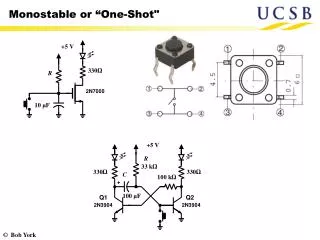
The Monostable • The monostable times using a capacitor (C1) which charges up through a resistor (R2)
Capacitors • Electronic buckets! • Non electrolytic • Generally < 1uF • Not polarized • Ceramic disc most common • electrolytic • Generally > 1uF • Polarized • Metal can (axial & radial)
Capacitor Charging t=RC Time constant – the rate at which a capacitor charges through a resistor + + Volts + + + + + + + + + + + + + + After one time constant, capacitor is at 0.6 of its full charge, and fully charged after 5 time constants Time
Capacitor Discharging t=RC Time constant – the rate at which a capacitor discharges through a resistor Volts Time
Starting the timer • Things start to happen when the voltage on pin 2 (trigger) is < 1/3 of supply • 3V in this case • R1 is a pull up resistor • Keeps the voltage atpin2 at near 9V when sw2 isn’t pressed • When pin is > 3V, pin 7(discharge) is connectsto 0V, discharging C1
When it ends • When pin6 (threshold) sees a voltage > 2/3 of supply • 6v in this case • When this happens, pin 7 (discharge) connects the capacitor back t0 0v again
The 556 • Two 555’s in one 14 pin package • Smaller and more power efficient • We will use one of these in our next project – a monstable (1 x 555) controlling an astable (1 x 555)