Pictorials in AutoCAD
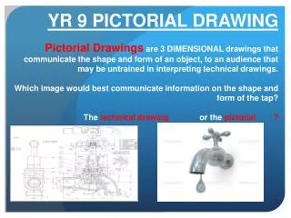
Pictorials in AutoCAD. Using AutoCAD to Create Pictorial Drawings. Learning Objectives. Use AutoCAD to draw an oblique of an object given orthographic views of the object Select the best orientation of an object in pictorial

Pictorials in AutoCAD
E N D
Presentation Transcript
Pictorials in AutoCAD Using AutoCAD to Create Pictorial Drawings
Learning Objectives • Use AutoCAD to draw an oblique of an object given orthographic views of the object • Select the best orientation of an object in pictorial • Define what makes a drawing a: cavalier oblique, cabinet oblique, isometric, axonometric, perspective, or orthographic views • Sketch pictorials of an object (either oblique or isometric) given orthographic views of the object • Use AutoCAD to generate Isometric Drawings of objects given the orthographic views of the object.
Types • Obliques • Cavalier • Cabinet • Axonometrics • Isometrics • Others • Perspectives
Cavalier Oblique • Front view true size • Receding Axis Angle (Normally 30°, 45° or 60°) is Variable • Depth dimension (receding axis) true size
Cabinet Oblique • Front view true size • Receding Axis Angle (Normally 30°, 45° or 60°) is Variable • Depth dimension (receding axis) half size
Angles in Oblique • Angles in front view are drawn true size • Other angles must be located using coordinates • Appearance of angles may be distorted
Obliques • Obliques are theoretical drawings. In reality, you can not actually view an object as an Oblique • Thin parts look very good as Obliques • Parts with angular features on multiple planes are difficult to draw as Obliques
Circles in Oblique • Drawn true size in front view • Drawn as ellipses on receding planes • Layout using a Rhombus
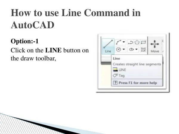
Drawing setup Drawing Aids Display control ZOOM General Concepts Keyboard Coordinates Editing and inquiry MOVE COPY TRIM Object Snap ENDPoint TANgent NEArest Today’s AutoCAD commands
Drawing Obliques in AutoCAD • Initially you should make a rough sketch of the object to get an idea of what your drawing should look like • Draw the front view as a flat orthographic view • Use the COPY command along with keyboard coordinates to place the front view along the receding axis to represent all frontal surfaces in the object • Connect the copies with lines representing the depth of the object. Remember to use OSNAP to assist in this process • Use ERASE and TRIM as appropriate to remove unwanted lines/arcs
Construction of an oblique • Draw the front view using normal AutoCAD commands and techniques
Construction of an oblique • Use the COPY command to replicate the front view to depict the depth Command: COPYE Select objects: [Other corner:[ 11 found Select objects:E <Base point or displacement>/Multiple: mE Base point: [ Second point of displacement: @.8<40E Second point of displacement: @1.8<40E Second point of displacement:E
Construction of an oblique • Use the COPY command to replicate the front view to depict the depth • ERASE the portions of the depth profiles which will not be seen.
Construction of an oblique • Add receding lines using OSNAP and the LINE command.
Construction of an oblique • TRIM and ERASE the remaining lines which would not be visible.
Isometrics • Axes equally separated (120°) • H, W, and D measurements are true size along iso. axes • Angles must be located by coordinates • Circles appear as ellipses on all surfaces
Drawing Isometrics in AutoCAD • Initially you should do a rough sketch of the object by hand to get an idea of what your drawing should look like • Switch the crosshairs to isometric mode • Draw the object using the LINE and ELLIPSE commands • Use F5 to toggle the current isometric plane • Use OTRHO and OSNAP to assist you in the drawing • TRIM or ERASE any portions which are not visible
Using isometric snap • If the crosshairs are not set in isometric mode, use the Drafting Settings dialog box. • Right click on snap button and choose settings
Drawing Ellipses • In isometrics, circular features which lie on the principal planes are shown as ellipses • These MUST be drawn using the ELLIPSE command with the Isocircle option
Exercise • Draw an Isometric pictorial of the object shown on the next slide using AutoCAD. • The grid is a .2” grid • Include centerlines
Think-Pair-Share • Spend 3 minutes to list what don’t you understand about pictorials [at least 3 things] • Merge your list with the person sitting next to you, AND add 1 new item to the list. You have 3 minutes. • Spend 5 minutes sharing the results with another pair of students, delete questions that you can answer for each other, AND prioritize the remaining questions your list • We will discuss the results, and answer any remaining questions as a class.