Download
1 / 22
220 likes | 435 Vues
Algorithm for Fusion of 3D Scene by Subgraph Isomorphism with Procrustes Analysis. Krzysztof Skabek, Przemysław Kowalski Instytut Informatyki Teoretycznej i Stosowanej PAN, ul. Bałtycka 5, 44-100 Gliwice e-mail: krzysiek@iitis.gliwice.pl. Contents. 1. Active vision

E N D
Algorithm for Fusion of 3D Sceneby Subgraph Isomorphism with Procrustes Analysis Krzysztof Skabek, Przemysław Kowalski Instytut Informatyki Teoretycznej i Stosowanej PAN, ul. Bałtycka 5, 44-100 Gliwice e-mail: krzysiek@iitis.gliwice.pl International Conference on Computer Vision and Graphics, ICCVG ‘2002
Contents 1. Active vision 2. Stages of 3D fusion 3. Graph representation and algorithms 5. Matching structure graphs 4. Algorithm for 3D Fusion 5. Experiments
The observed 3D scene Platform movements Active Vision Platform
Purpose: Obtaining a complete 3D representation of the scene and relations between components of the scene basing on a set of 3D frames from multiple viewpoints. Assumptions: No a-priori information about objects of the scene. Unknown location of the viewpoint. We focus on polyhedral objects.
Methods of 3D fusion Architecture of Active Vision Sensing Planning 3D model Mision planning Location: x,y,z, Navigator Model integration Pilot Image preprocessing Act Controller camera camera Engines
3D Fusion of Multipoint Views 3D Fusion – integration process of objects in 3D scene on the basis of visual information from several viewpoints.
Comparing the view and the model Exact viewpoint loc. Updating the model Hypothesis aboutthe scene objects Checking the completeness Stages of 3D Fusion Vision device Current view 3D model Viewpoint loc. Prediction Corection Knowledge of the scene Navigation to a new viewpoint
Preprocessing of Visual Information • Improvement of image quality, noise reduction • Image segmentation, extraction of lines, segments,vertices: Susan, Hough Methods • Stereo matching, depth map: active contours, hardware support (ranging lasers, depth sensors) Algorithms prepared for Khoros platform
Viewpoint parameters • T – vector of translation (3×1), • R – rotation matrix (3×3, orthogonal) • s – scale (scalar) Relation between coordinates of point P: Pw – global coordinates, Pk – coordinate system of the camera Pk = R(Pw –T)s
Graph representation of 3D scene 4 7 Contour graph 4 6 1 3 1 3 5 2 2 Face graph
Subgraph Isomorphism 3 Weak Subgraph Isomorphism 2 3 3 2 3 2 3 4 2 3 2 3 2 2 3 3 2 3 3 4 3 Graph Isomorphism Graph Isomorphism 3 3 2 2 2 2 3 3
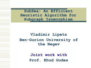
Detection of Graph Isomorphisms • Permutation method • Clique detection method • Ullman method • A* method (error correction) • Decision tree method Algorthm with analysis of 3D structure deformation (decision tree, consistency checking, branch pruning, geometric similarity)
Similarity of Shape – Procrustes analysis Rotation (R) Translation (T) Scale (S) --- - object A --- - object B --- - A to B matching D2(A, B) = || B – S·R·A – T ||2
0 1 2 3 4 5 6 0 1 n 2 ISOMORPHISMS 3 4 Implementation of 3D Fusion(matching contour graphs) V Stage I: Generation of groups of vertices (quadruplets) fulfilling conditions: • Procrustes distance < • Preserving edge topology Stage II:(for eqch group of vertices from stage I) Calculation of local transformation (TL RL SL) Matching the remaining vertices: • Local Procrustes distance < • Preserving edge topology Calculation of exact transformation (T R S)
B F A D 5 C E GMi Implementation of 3D Fusion(model updating) 1 2 B F 3 A D 5 4 C 6 E GIi GMi-1
Implementation of 3D Fusion(hypothesis of the scene objects) Introducing unconfirmed elements. Hypothesis of scene objects: • Connecting edges • Closing faces • Connecting partial faces • Ground plane detection • Completing vertical faces
Conditions of experiments Total transformation error consists of: rotation, translation, scale Tolerance of rotation (R – matrix of rotation error): R = RR Estimation of rotation error: = ½ [1 – cos() ]½ Assumed value of rotation error: = 0.1 for 16°
Graph representation of 3D scene II Contour graph: Face graph: • a set of vertices in the scene • a set of edges between vertices • coordinates (x,y,z) of vertices • a set of faces in the scene • a set of connections between faces • parameters of faces • parameters of connections between faces
Implementation of 3D Fusion Input data: GIi– contour graphs for views (i=1..n) Ti Ri Si – estimated transformation (from navigation unit) i – transformation tolerance (for navigation unit) i – observation tolerance (for optical unit) Output data: GMn – Contour graphs of model Ti Ri Si – computed transformation First step of fusion: GM1 GI1