3D Scene Calibration for Infrared Image Analysis
190 likes | 316 Vues
This paper discusses the advanced methodologies for 3D scene calibration aimed at optimizing infrared image analysis within fusion research contexts. It addresses the challenges posed by complex thermal scenes, depth of field, and variable optical properties of materials. The objective is to establish a reliable link between pixel data and 3D models of in-vessel components. Key features include image stabilization, noise reduction, and dynamic intensity-based masking techniques. The results contribute to real-time processing capabilities and improve data quality for robust analysis in tokamak experiments.

3D Scene Calibration for Infrared Image Analysis
E N D
Presentation Transcript
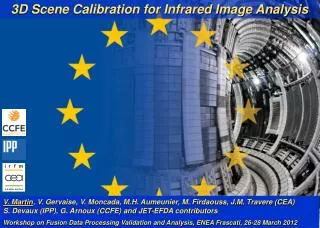
3D Scene Calibration for Infrared Image Analysis V. Martin, V. Gervaise, V. Moncada, M.H. Aumeunier, M. Firdaouss, J.M. Travere (CEA) S. Devaux (IPP), G. Arnoux (CCFE) and JET-EFDA contributors Workshop on Fusion Data Processing Validation and Analysis, ENEA Frascati, 26-28 March 2012
3D IR Scene Calibration JET #81313 KL7 (images in DL) • Issue: a complex thermal scene • Wide angle views with high geometrical effects: depth of field and curvature • Many metallic materials (Be, W) with different and changing optical (reflectance) and thermal (emissivity) properties • Objective: Match each pixel with the 3D scene model of in-vessel components for: • getting the real geometry of the viewed objects • reliable linking between viewed objects and their related properties • Applications • Image processing (e.g. event characterization) • IR data calibration: Tsurf = f(material emissivity) Bulk Be W coated CFC Bulk Be Bulk Be Be coated linconel W coated CFC Bulk W
Methodology • Calibration chain NUC Dead pixel Map Reference image 2D/3D scene models Knowledge base of the thermal scene Image Correction Image Stabilization 2D/3D Scene Model Mapping Image Processing Registered & Geo-calibrated Image Camera
Illustration of Motion in Images • Camera vibrations lead to misalignments of ROIs (PFC RT protection) = false alarms or worth missed alarms • Image stabilization is a mandatory step for heat flux deposit analysis based on Tsurf(t)-Tsurf(t-1) estimations
Image Stabilization • Important factors for method selection • Deformation type: planar (homothety), non-planar • Target application: real-time processing, off-line analysis • Data quality and variability: noise level, pixel intensity changes, image entropy • Required precision level: pixel, sub-pixel • Applications in tokamaks (non-exhaustive list)
Image Stabilization • Classical Methodology • Feature Detection • Local descriptors: Harris corners, MSER, codebooks, Gabor wavelets (see Craciunescu talk), SIFT, SURF, FAST… • Global descriptors: Tsallis entropy (see Murari talk), edge detectors… • Fourier analysis: spectral magnitude & phase, pixel gradients, log-polar mapping… • Feature Matching • Spatial cross-correlation techniques: normalized cross-correlation, Hausdorff distance… • Fourier domain: normalized cross-spectrum and its extensions • Transform Model Estimation • Shape preserving mapping (rotation, translation and scaling only) • Elastic mapping: warping techniques… • Image transformation • 2D Interpolation: nearest neighboor, bilinear, bicubic… See Zitova’s survey, Image and Vision Computing, vol. 21(2003), pp. 977-1000
Proposed Algorithm • Masked FFT-based image registration [1] • Deterministic computing time • Accelerating hardware compatible algorithm (e.g. FFT on GPU) → real time applications • Local analysis with dynamic intensity-based pixel masking (e.g. mask the divertor bright region) • with sub-pixel precision [2] • Slow drift compensation • and dynamic update of the reference image • Robust to image intensity and structural changes • Evaluation of the registration quality over time [1] D. Padfield, IEEE CVPR’10, pp. 2918-2925, 2010 [2] M. Guizar-Sicairos et al., Opt. Lett., vol. 33, no. 2, pp. 156-158, 2008
Principle of Fourier-based Correlation Iref It NCC(Iref, It) max (NCC(Iref, It)) • Let Iref a reference image, It an image at time t and DFT the Discrete 2D Fourier transform such as It ( x , y ) = Iref ( x-x0 , y-y0 ) • NCC is the Normalized Cross Correlation figure (image) and the position of the peak gives the coordinates of the translation ( x0 , y0 )
Sub-pixel Precision • Up-sample k times the DFT of NCC (trigonometric interpolation): • The peak coordinates ( x0 , y0 ) give F the translation with 1/k pixel of precision:
Reference Image Updating • Goal: maintaining a good reliability of the motion estimator (NCC peak value) while image appearance changes during the pulse.
Reference Image Updating • Solution: use the NCC peak value to trigger the update of Iref such as: updateIref updateIref updateIref updateIref NCC peak too low, no Iref update
Results • JET #81313 (MARFE, disruption), KL7, 480x512 pixels, 50 Hz, 251 frames k=1/4 pixel
Results • JET #80827 (disruption), KL7, 128x256 pixels, 540 Hz, 13425 frames k=1/2 pixel
Results • JET #82278, KL9B (slow drift), 32x96 pixels, 6 kHz, 4828 frames 96 pixels 32 pixels
Computational Performance • High frame rate performance using GPU 256x256, k=1/4 → 700 fps
From 2D to 3D • Challenge • transform pixel coordinates into machine coordinates: (x, y) (r, θ, φ) • Method • Ray-tracing method from 3D/simplified CAD files
3D Scene Model for Image Processing S. Palazzo, A. Murari et al., RSI 81, 083505, 2010 Z Map (depth) 1 mm 2 2m 1 Blobs 1 & 2 must not be merged! 7m 2 1 2 V. Martin et al.
Integrated Framework NUC Dead pixel Map Reference image 2D/3D scene models Knowledge base of the thermal scene Load/save translations Used for event triggering Set mask Image Correction Image Stabilization 2D/3D Scene Model Mapping Image Processing Registered & Calibrated Image Used for temperature evaluation Camera Set sub-pixel precision factor Used for PFC protection • An integrated software for IR data stabilization & analysis Plasma ImagiNg data Understanding Platform (PINUP)
Conclusion • Summary • Complex IR scenes require a new approach for reliable data analysis including image stabilization and 3D mapping. • A robust and fast image stabilization algorithm with sub-pixel precision has been proposed. • A first demonstration of 3D model for IR data analysis has been successfully carried out at JET on the wide-angle ITER-like viewing system (KL7). • An integrated software (PINUP) implementing these features is available for users upon request. • Outlook • Test of the stabilization algorithm on visible imaging data (JET KL8) with rotation compensation • Full integration of 3D scene models into PINUP • Improvement of image processing algorithms (e.g. hot spot detection) with 3D information