Site Calibration for 3D GPS Operations
330 likes | 508 Vues
Site Calibration for 3D GPS Operations. Presenter Name. GPS Site Calibration. Site reconnaissance Control point availability GPS base station location Performing the Calibration. Control point availability. Control points are measured to “calibrate” the site for GPS-based systems

Site Calibration for 3D GPS Operations
E N D
Presentation Transcript
Site Calibration for 3D GPS Operations Presenter Name
GPS Site Calibration • Site reconnaissance • Control point availability • GPS base station location • Performing the Calibration
Control point availability • Control points are measured to “calibrate” the site for GPS-based systems • Do control points exist on site? • Check the site plans for control point lists and locations • You need a minimum of 3 and 5 or more are recommended • For more information, contact: • Land Surveyor • Engineering firm
GPS base station locations – considerations • Obstructions • Setup GPS base station antenna with 360° view of the sky. If limited try to set up with clear visibility to the south. • GPS 55° latitude limit • Glonass 65° latitude limit • Avoid sources of multipath (deflection of the GPS satellite signal) • Chain link fence • Trees • Flat, reflective surfaces – metal roofs, glass windows, water, etc • Setup GPS base radio link for maximum broadcast range • Elevate the radio antenna to increase range • Correct antenna (high gain and low gain) • Avoid sources of RF interference (Microwave, Power lines, etc)
GPS Site Calibration • What is it… • Requirements
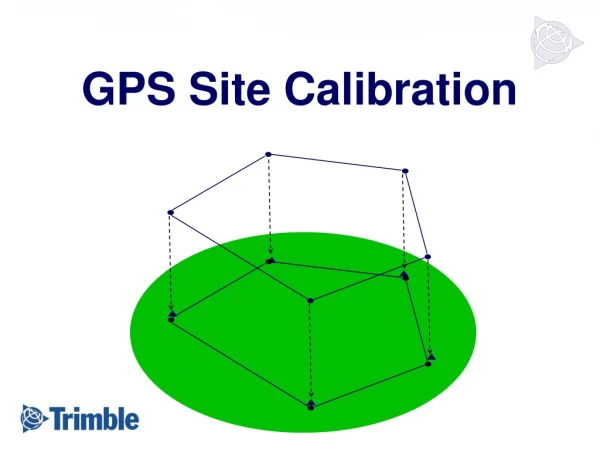
GPS Coordinates NEE GPS Site Calibration • What is a site calibration? • A measurement procedure that defines the relationship between GPS coordinates and local coordinates • GPS in Latitude, Longitude, and Ellipsoid Height • Local Coordinates in Northing, Easting, Elevation (MSL) • We are pairing coordinates on a sphere surface and to those on a flat planar surface
= GPS observation = Control Point GPS Site Calibration • Why is a site calibration required? • Allows GPS-based rover systems to work in your local site coordinate system • What is needed for site calibration • Onsite control base on local coordinates
GPS Site Calibration • The calibration locally adjusts the • Projection • Includes shift grids, projection grids, datum grid • Includes Azimuth orientation (e.g.North or South) • Datum • Site Calibration is comprised of 2 parts • Horizontal adjustment • Rotate, Translate, & Scale • Vertical adjustment • Block shift & Tilted Plane • Geoid
GPS Site Calibration • Measuring a Site Calibration will assume • Projection – Transverse Mercator • Datum – WGS84 • If you want to use an alternative to this, then a DC file containing that information should be created and used as the starting point e.g. State Plane etc. • Can then be localized through site calibration
Horizontal Translation • Points shifted X & Y • Same Amount & Direction • 1 Control Point
Horizontal Rotation • Rotation about project centroid • 2 control points
Horizontal Scale • Ratio • GPS to Local Coordinates • 2 Control Points
Residuals • Residuals • Best effort translation between pairs (Control & WGS-84) • SCS900 has a Tolerance for Calibration • Value should be 50% of acceptable project tolerance • Tolerance used to test calibration result worst residual
Calibration Requirements • Single point site calibration Requirements • Requires a single, 3D control point – known or “arbitrary” • Single point defines coordinate system orientation • Used when control does not exist • Recommended for initial site topos and for quick stockpile or volume topos etc • Recommend measuring control points to tie to design reference frame later • Not recommend on long linear projects = GPS observation
= GPS observation = Control Point Calibration Requirements • Multi-point site calibration Requirements • Minimum of 3 (3D) control points • Recommend 5+ control points with good geometry for better results • Combination of horizontal and vertical points - Minimums • 3 horizontal control points & 3 vertical control points – or – • 1 vertical + 3 horizontal + Geoid model • Used when control exists and references a design frame
Control Point Locations • 3 points • will work, but yields only 3 baselines • Geometry could be weak • Control should encompass the entire site
Control Point Locations • 4 Points • Better, 6 baselines • 4th point - independent height check • Geometry is stronger
Control Point Locations • Optimal control- • Multiple control points • Geometry strongest, balanced • Points encompass the site. • This example - 7 points, 18 baselines.
Control Point Locations • Control point network geometry is key = Poor network geometry = Ideal network geometry • Enclose the project area with control • More control points and good network geometry can improve site calibration results and identify problems early
Tilted Plane • Tilted Plane • Effectively models the effect of the local Geoid i.e. local variations in gravity over the site • Minimizes height residuals on control points after block shift • User selectable when to occur in SCS900 • SCS900 has a minimum of 3 points, default is 5 • With only 3 points there is no check and it will zero all residuals to create the tilted plane • Occurs after 2 points in Survey Controller to eliminate height residuals after block shift • SCS900 and Survey Controller will only agree when the tilted plane has been applied in both
Details of how this works • Measured Points • Provided local coordinates • The difference between them • Some high, some low compared to average shift • Block Shift from measured to local using average shift • Rotate i.e. Tilt the plane through the measured points to minimize residuals and get a best fit of measured control to local control • In an ideal world we would get a perfect fit • We don’t have an ideal world so we get residuals after the tilted plane – those residuals dictate whether we are in tolerance for the Site Calibration or not.
Geoids • Trimble GeoData folder added in SCS900 v2.3 • Geoids will apply at Site Level • Store multiple Geoids in Trimble Geodata folder • If no Geoids exist in the Trimble Geodata folder then you will not be asked this question
Geoids • Should I use a Geoid model? • Geoids will never hurt • Geoids will allow you to go outside your project calibration • Geoids allow for fewer vertical control points • Provides better detection of errors in control • Recommended on long linear projects
h N Geoid Height (GEOID03) Ellipsoid (WGS84) Geoid Geoids • A geoid height is the separation between the Ellipsoid and the Geoid at any location on the earths surface H = Orthometric Height h = Ellipsoidal Height (WGS84) H = h - N N = Geoid Height (GEOID 03) TOPOGRAPHIC SURFACE H A B
Geoids • Geoid Model (Nm) • Approximates Geoid • Geoid Values (N) • Computed from BM Elevations (h-H=N) • ∆N at each Control Point
Geoids • Tilted Plane through ∆N
Shift Grids • SCS900 now supports SHIFT GRIDS • There are three different types of Shift Grids in Europe • Belgium and Netherlands use SHIFT GRID FILES • UK uses PROJECTION GRID FILES • France uses DATUM GRID FILES
Shift Grids • SHIFT GRID FILES • A standard projection is used to get grid coordinates and then the shift grids are applied to get the correct national coordinates. One .sgf file contains both northings and eastings shifts • PROJECTION GRID FILES • A standard projection is used to get grid coordinates and then the shift grids are applied to get the correct national coordinates. One .pgf file contains northings and another .pgf file contains eastings shifts • DATUM GRID FILES • The shift is applied before the projection. One .dgf file contains the datum shift
GPS Site Calibration • Improving my calibration results • Continue to calibrate on additional control points • Change tolerance • Edit Calibration Components after measuring all control points for the calibration by switching on/off Hz or VT components… • Careful, it is extremely risky to remove one component of a point unless Horizontal and Vertical components of control were established under separate processes
Moving the GPS base station • Before calibration – no problem • After calibration – location requirement • Must be moved to control point • Control used during the calibration • Control measured before moving based and using calibration • Same rules for calibration obtained under VRS
Conclusion • In conclusion, remember these key points • Good Base Station location for good observables • Adequate number of control points (5+) • Good Geometry among control points