Download
1 / 17
170 likes | 300 Vues
This workshop, held on November 9-10, 2009, at CERN, focused on the cryogenic and vacuum sectorisation of the Superconducting Proton Linac (SPL). Organised by Vittorio Parma, the event aimed to address the conceptual design of the SPL, including low-power and high-power options. Key discussions included cryogenic cooling layouts, insulation vacuum needs, operational risks, and maintenance challenges. Attendees explored various sectorisation schemes, striving to develop robust solutions for optimal machine performance and reliability.

E N D
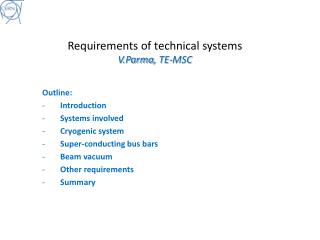
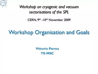
Workshop on cryogenic and vacuum sectorisations of the SPLCERN, 9th -10th November 2009Workshop Organisation and Goals Vittorio Parma TE-MSC
Layout injector complex SPS PS2 ISOLDE PS SPL We are here today Linac4
The SPL study Goals of the study (2008-2012): • Prepare a Conceptual Design Report with costing to present to CERN’s management for approval • …aimed at a start of construction of the low power SPL (LP-SPL) optimized for PS2 and LHC at the beginning of 2013 110 m 0.73 GeV 186 m 1.4 GeV 0 m 0.16 GeV 427 m 4 GeV 10 x 6 b=0.65 cavities 13 x 8 b=1 cavities 5 x 8 b=1 cavities High b cryomodules High b cryomodules Debunchers Medium b cryomodule To PS2 Ejection From Linac4 Length: ~430 m TT6 to ISOLDE LP-SPL beam characteristics
The SPL study (cont.d) • … with an optional possibility of a later upgrade to 5 GeV and multi MW high power beam (HP-SPL). ~500 m 5GeV 110 m 0.73 GeV 186 m 1.4 GeV ~300 m 2.5 GeV 0 m 0.16 GeV High b cryomodules Ejection 10 x 6 b=0.65 cavities 6 x 8 b=1 cavities 5 x 8 b=1 cavities High b cryomodules High b cryomodules Medium b cryomodule Debunchers To PS2 Ejection From Linac4 12 x 8 b=1 cavities to Eurisol Length: ~500 m TT6 to ISOLDE HP-SPL beam characteristics
Construction of a cryo-module prototype (as part of the SPL study) today
Topics for discussion • What is already decided (not for discussion today): • Cavities cooled in saturated superfluid helium (T~ 2K, P~ 3.1 kPa) • Cavities RF frequency: 704 MHz • One surface cryoplant at mid lenght of the SPL: • ~ 6 MW @ 4.5K for LP-SPL (~ 20 MW @ 4.5K for HP-SPL) • What is to be discussed today: • Cryogenic cooling layouts and schemes and consequences on machine cryostats: • Single “continuous” cryostat vs. fully “segmented” cryostat with cryo distribution line • Intermediate variants • Vacuum systems and consequences on machine cryostats: • Insulation vacuum and need for vacuum barriers • Cavity/beam vacuum and need for gate valves • possibly also coupler vacuum • We need to learn from the experience of other machines and labs
Road map of the workshop • Machine availability: • “work-horse” in the injection chain • 100% availability not viable,.What is achievable? And at which cost? • Reliability of built-in components and operational risks (degraded performance without intervention) • Typical faults expected on: • Cavities • Couplers • Tuners • .. • Operation with degraded performance and mitigating measures: • Degraded performance of cavity/ies reduced energy • Degraded optics (quads, steerers) reduced beam quality • Operating with leaks • ... • Built-in redundancy (e.g. need for installed spare cryo-modules) • Maintainability: • Radioactive cool-down time • Warm-up/cool-down . Time and reliability. Need for partial or complete warm-up of strings to replace built-in components or even one cryo-module • Accessability of components for regular maintenance or repair • Design complexity of compared solutions • Operational complexity (e.g.cryogenics with 1.7% slope) • Installation and commissioning • Coping with incidents (MCI). Loss of beam and/or insulation vacuum : • helium leaks • Air leaks • Cost differences between options • - …
Goals • Primary goals: • Identify the main operational and intervention scenarios for the cryogenics and vacuum systems of the SPL • Elaborate an exhaustive technical and economical comparison between single “continuous” cryostat and “segmented” cryostat with cryo distribution line • Possibly reccomend a choice between the two options • Define a “baseline” cryogenic distributions scheme and vacuum sectorisation • Elaborate, if necessary, a list of further developments for making a choice • Other goals: • Identify advantages for alternative sectorisation schemes (intermediate solutions) • Technical comparison between layouts with warm and cold magnets • Identify other machine architectures to be explored for an improved sectorisation (e.g. alternative optic schemes)
Possible cryogenic feeding Cryo-plant 1.7% tunnel slope CIB 10 β=0.65 + 5 β=1 cryo-modules 6 β=1 cryo-modules 17 β=1 cryo-modules + 2 demodulators Isolde extraction Eurisol extraction CIB Cryogenic Interconnect Box Cryo Unit Cryogenic bridge
Possible cryogenic feeding Cryo-plant CIB 10 β=0.65 + 5 β=1 cryo-modules 6 β=1 cryo-modules 17 β=1 cryo-modules + 2 demodulators Isolde extraction Eurisol extraction CIB Cryogenic Interconnect Box Cryo Unit Cryogenic bridge
Possible cryogenic feeding Cryo-plant CIB 10 β=0.65 + 5 β=1 cryo-modules 6 β=1 cryo-modules 17 β=1 cryo-modules + 2 demodulators Isolde extraction Eurisol extraction CIB Cryogenic Interconnect Box Cryo Unit Local Cryo Distribution Line (~80m)
Possible cryogenic feeding Cryo-plant CIB 10 β=0.65 + 5 β=1 cryo-modules 6 β=1 cryo-modules 17 β=1 cryo-modules + 2 demodulators Isolde extraction Eurisol extraction CIB Cryogenic Interconnect Box Cryo-module Units Cryogenic Distribution Line
“continuous” cryostat • “Long” and “continuous” string of cavities in common cryostat • Cold beam tube • “straight” cryogenic lines in main cryostat • common insulation vacuum (between vacuum barriers, if any present) String of cryo-modules between TSM Technical Service Module (TSM) Cold-Warm Transition (CWT) Insulation vacuum barrier Warm beam vacuum gate valve
“bridged” cryostat • Variant of the continuous cryostat • Warm beam zones, 2 CWT at every cryo-module • cryostat “bridges” between adjacent cryo-modules • “bent” cryogenic lines through “bridges” CDL not needed • common insulation vacuum (between Vacuum Barriers, if any present) Cryostat “bridge” with integrated cryo-lines Single cryo-modules Technical Service Module (TSM) Cold-Warm Transition (CWT) Insulation vacuum barrier Warm beam vacuum gate valve
“segmented” cryostat • Cryostat is “segmented”: strings of (or single) cryo-modules, 2 CWT each • Warm beam zones • Cryogenic Distributio Line (CDL) needed • Individual insulation vacuum on every string of cryo-module (Vacuum Barriers, w.r.t. CDL) Cryogenic Distribution Line (CDL) String of (or single) cryo-modules Technical Service Module (TSM) Cold-Warm Transition (CWT) Insulation vacuum barrier Warm beam vacuum gate valve