Detector R&D: Belle DAQ System
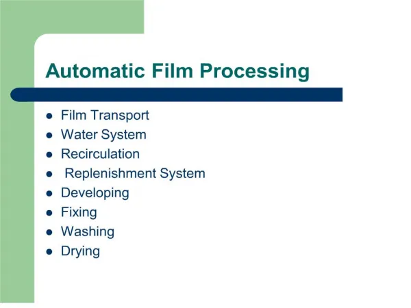
Detector R&D: Belle DAQ System. Belle DAQ Overview. Main coverage by “DAQ” Data flow: signal digitizer storage Timing: trigger timing distribution. trigger decision. trigger clock F/O. system clock. TDC. Readout PC. detector frontend. TDC. TDC. detector frontend. TDC.

Detector R&D: Belle DAQ System
E N D
Presentation Transcript
Detector R&D:Belle DAQ System New Hadrons with Various Flavors
Belle DAQ Overview • Main coverage by “DAQ” • Data flow: signal digitizer storage • Timing: trigger timing distribution triggerdecision triggerclock F/O systemclock TDC ReadoutPC detectorfrontend TDC TDC detectorfrontend TDC ReadoutPC Eventbuilder TDC TDC detectorfrontend TDC ReadoutPC TDC TDC Eventbuilder OnlineAnalysis PC … … … detectorfrontend TDC ReadoutPC Eventbuilder TDC TDC
Belle DAQ Diagram • Coverage list • Signal digitization • Digitized data readout • Run control • HV control • Data quality monitor • Event building • Online data analysis • Timing distribution
Belle DAQ Virtual Tour – 1 Signal digitizer(TDC) PMC-sized CPU signal digital via LAN Signal digitization and data transmission
Belle DAQ Virtual Tour – 2 signal digital timing timing Trigger Timing Redistributor Trigger timing redistribution
Belle DAQ Virtual Tour – 3 VME9U-sized Platform“COPPER” • TDC module× 2 • Trigger timing redistributor • PMC-sized CPU COPPER Detail of the COPPER is described later.
Belle DAQ Virtual Tour – 4 + = After cabling of input signals COPPER crate
Belle DAQ Virtual Tour – 5 Digitized data readoutby the PMC-sized CPUare sent to crate readoutPCs via a network switch. Crate readout
Belle DAQ Virtual Tour – 6 Fragmented data fromeach crate readout PCare sent to event buildingPCs to be combined toa single event record. Finally, the data aresent to online analysisPCs and recordedto hard disks. Event building PCs / Online analysis PCs
Belle DAQ Virtual Tour – 7 timing • Trigger timing distribution • System clock distribution • Busy collection Fanout timing timing crate rear Trigger timing distribution – again
Advertisement: COPPER System • We have developed several excellent DAQ technologies by ourselves. • Among them, today, we like to advertise the “COPPER System” to you for its … • High flexibility to fit your experiment, • Wide acceptance of L1 rate up to 30kHz, • Broad bandwidth of > 80MB/s, • Less DAQ deadtime with equipped pipeline, and • Less requirement of knowledge in writing readout software.
Why We Developed COPPER? • KEKB / Belle upgrade plan • KEKB luminosity increases: 1.71034 81035cm-2s-1 more L1 rate: 500 Hz10-30 kHz • Belle upgrades more readout channels: 40 kB/ev 200-300 kB/ev • Limit of the present Belle DAQ • Deadtime fraction of the present FASTBUS-basedDAQ will be extrapolated to ~20% even @ L1=1kHz. Call for new DAQ accommodates with L1=30kHz.
COPPER FINESSE×4Add-on modules to theCOPPER. Responsibleto digitize the input signalsand output them to pipelineFIFOs on the COPPER. Online CPUAdd-on module to the COPPER.Responsible to readout the COPPERFIFO, to process and format the data,andto send the data to external PC viathe network. RadiSys EPC-6315 • Intel P3 800 MHz • 256 MB memory • Network boot • RedHat Linux 9 Trigger timing moduleAdd-on module to the COPPER. Responsibleto receive trigger timing and system clock fromupstream and to deliver them to the FINESSEs. 100BaseT port×2 Data transmission lineand control line.
COPPER Block Diagram COPPERFIFO add-onmodules PMC modules FINESSE PMC CPU PCI bus Local bus FINESSE to external PC Network I/F from sub-detector Bridge FINESSE Timing Module FINESSE
FINESSE SuperBelle: composite of different kinds of sub-detectors Flexible designfitting to the detector Detector ARequires ADC Detector BRequires TDC Detector CRequires buffer ADC FINESSE TDC FINESSE Buffer FINESSE Predefinedprotocol COPPER COPPER COPPER Common readoutafter the FINESSE The COPPER/FINESSE system enables us/you toconcentrate on the digitizer part without worryingabout implementation of the readout part.
FINESSE Catalogue 2008 Digital BufferFINESSE 65 MHz 8chFADC FINESSE Pixel ReadoutFINESSE 500 MHz 2chFADC FINESSE USB I/F FINESSE(Debug use) TDC FINESSE w/ AMT3 TDC chip TDC FINESSEw/ HPTDC chip TDC FINESSEw/ Vertrx5 FPGA Dry runFINESSE Several functions ofFINESSEs are readyfor hitchhikers.
History of “Project COPPER” Red items will bedescribed in detaillater. • 2002-2003 • Start of design from a scratch. • First version of the COPPER. • 2004 • Revision to the COPPER-II. • Minimal performance study. • 2005 • Decision to replace entire Belle DAQ with the COPPER-II. • To reduce the DAQ deadtime, and • To make an in-situ system test toward SuperBelle. • R&D of TDC FINESSE toward the DAQ replacement. • Replacement of Belle EFC readout with the COPPER-II/FINESSE (6).
History of “Project COPPER” • 2006 • System test in a full scale test bench. • Replacement of Belle CDC readout partially with the COPPER-II/FINESSE. • System test in situ. • 2007-2008 • Replacement of Belle CDC readout with the COPPER-II/FINESSE (89); intensive in-situ study. • Replacement of Belle ACC readout with the COPPER-II/FINESSE (24). • Replacement of Belle TRG readout with the COPPER-II/FINESSE (26). • Start of revision to the COPPER-3.
Minimal Performance Study (2004) @ 416 bytes/ev/FINESSE(typical data size for SuperBelle CDC) COPPER Compressedby 10% Dry runFINESSE CPU 40 Design Max L1 rate@ SuperBelle Dry runFINESSE 30 Trigger Timing Mod. 20 Dry runFINESSE AcceptedL1 rate [kHz] Typical L1 rate@ SuperBelle 10 Ethernet Dry runFINESSE 0 10 20 30 40 InputL1 rate [kHz] The COPPER works well even under the severest L1 rate (>30kHz)of the SuperBelle.
R&D of the TDC FINESSE (2005) Req. AMT3 ATLASMUON TDC The AMT3 has a similar performance as the Belle FASTBUS TDC. It enables a seamless transition from the FASTBUS to the COPPER-II. Equipped pipeline • Channel buffer= 4 edges× 24ch • L1 FIFO = 256 edges • ReadoutFIFO = 64 edges TDC chip selection = AMT3
AMT3 FINESSE (2005) • “Tandem” FINESSE • FASTBUS TDC (manufactured by LeCroy) has6 cable-connectors 16 channels = 96 channels. • Not to change the cables configuration, we developed “tandem” FINESSE (occupying 2 slots), with 3 connectors. • AMT-3 TDC chip • Spartan3 FPGA • AMT3 register control. • Data readout from the AMT3 output FIFO. • Data formatting (header/footer etc.). • Data output to the COPPER FIFO. • I/F to the COPPER local bus.
Full Scale Test Bench (2006 –) Networkswitches Pulse Generator (signal & trigger source) COPPER/AMT36 crates • Full-scale data flow simulation from the PG to the readout PCs. • Detailed study of the AMT3 behavior (including debug). • Establishment of the global control scheme.
In-Situ Study with Belle CDC (2006) • Word-by-word comparison of readout data by the FASTBUS and the COPPER-II/AMT3. COPPER×16 CDC from CDC Q-to-T AMT3 Residual distribution 4 2 AMT3 – FASTBUS (unit: AMT3 LSB) Daisy-chain FASTBUS 0 AMT3 FASTBUS Resolution0.61 LSB (RMS) -2 -4 LeCroy TDC×16
Full Replacement of CDC DAQ (2007) 6 COPPER crates 89 COPPERs Readout PCs Q-to-T TX SW Boot SW Q-to-T TX SW Localevent building PC Boot SW Q-to-T TX SW Boot SW Q-to-T TX SW Boot SW Q-to-T TX SW Boot SW Q-to-T TX SW Boot SW
Reduction of DAQ Deadtime (2007) S.Y.Suzuki Typical data size FASTBUS ~29.5 μs Deadtime per event (μs) We achieved deadtime reduction by 90% by installing pipelinedDAQ with COPPER. COPPER-II/AMT3 ~2.8 μs # of hits/TDC
COPPER Is Not Difficult int main(int c, char *v[]) { int fd; fd = open(“/dev/copper”, O_RDONLY); /* put your FINESSE initialization here */ while(1){ static char buf[1024*1024]; read(fd, buf, sizeof(buf)); /* data read */ } } That’s all. • Several functions of FINESSEs are ready for you. • Thanks to an excellent device driver, the COPPER can be read out quite easily.
Timing Distribution for COPPER • SEQ • Event sequence controller. • TT-IO • Clock / trigger repeater from the SEQ. • Busy collection. • TT-SW • Clock / trigger fan-out. Busy fan-in. • TT-SW can be cascaded. • TT-RX • Clock / trigger fan-out to the FINESSEs. • Busy collection from FINESSEs. KEK-VME 9U Crate VME6U VME6U VME6U COPPER FINESSE As Belle uses many COPPERs (~150),we have developedan special timing distribution system,which may look (and really is) complicated. CAT-5 serial busconnection FINESSE TT-SW TT-IO TT-RX SEQ TRG FINESSE FINESSE TT-RX If # of COPPERs you use is small,we can proposean alternative simple modulefor the timing distribution. TT-RX … TT-RX M.Nakao
COPPER Is Not Difficult Fan-out to 4FINESSEs Clock / trigger timing NIM level over LEMO cable Y.Igarashi, K.Tauchi • “Simple trigger board” plugged on the COPPER • Suitable for a compact experiment.
COPPER Users Please join us andenjoy data takingwith the COPPER system. Belle: Half of the DAQ is COPPER’ized SuperBelle: Planning to utilize the COPPER. T2K: Beam monitor muSR and YOU
COPPER-3 • COPPER-II COPPER-3 • Replacement of terminating parts with recent ones. • Fix jumper patches by pattern layout. • Upgrade onboard Ethernet chip to Gbit-Ethernet. • and others. • We confirmed the COPPER-3 is fully compatible with the COPPER-II using AMT3 FINESSE.
Brief Prospects of SuperBelle DAQ On/In detector Electronics hut COPPER Data and timing link digitizer FPGA Link RXFINESSE Rocket I/O? Preliminary design
Summary We developed a new readout system “COPPER” toward the higher luminosity HEP experiment. We developed a TDC FINESSE equipped with an AMT3 chip to readout the Belle CDC; In the in-situ study, we found the COPPER/FINESSE/AMT3 system showed high compatibility to the FASTBUS DAQ system. The COPPER is quite easy to operate. We introduce you to join us and to be a member of COPPER user team. We are designing COPPER-3. Design of a new FINESSE for SuperBellehas also been started. In SuperBelle, one of key roles of the FINESSE will be data RX.