Q-tuning Schemes
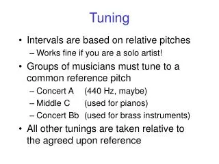
ELEN 622 (ESS). Q-tuning Schemes. Applications for continuous time filters. Read channel of disk drives -- for phase equalization and smoothing the wave form. Top view of a 36 GB, 10,000 RPM, IBM SCSI server hard disk, with its top cover removed. Receivers and Transmitters in wireless


Q-tuning Schemes
E N D
Presentation Transcript
ELEN 622 (ESS) Q-tuning Schemes
Applications for continuous time filters Read channel of disk drives -- for phase equalization and smoothing the wave form Top view of a 36 GB, 10,000 RPM, IBM SCSI server hard disk, with its top cover removed.
Receivers and Transmitters in wireless applications -- used in PLL and for image rejection 6185i digital cell phone from Nokia.
All multi media applications --Anti aliasing before ADC and smoothing after DAC CMP-35 portable MP3 player
How to build a filter • OpAmps - Low frequency, high linearity • OTAs - Medium high frequencies, medium linearity • Passive components - High frequency • Transmission lines - Extremely high frequency
Advantages of differential Circuits • Double the signal swings • Better power supply and substrate noise rejection • Higher output impedance with conductance cancellation schemes • Better linearity due to cancellation of even harmonics • Partial cancellation of systematic errors using layout techniques • Availability of already inverted signals
Disadvantages of differential Circuits • Duplication of circuit requires double the area and power • Additional circuitry to tackle common mode issues
Common mode issues • Output DC common mode voltage should be stabilized (otherwise, the voltage may hit the rails) • Common mode gain should be small (otherwise, positive feedback in a two integrator loop becomes stronger)
Common Mode Feed Forward • Can decrease common mode gain even at higher frequencies • Does not have stability problems • Cannot stabilize the output DC voltage
Common Mode Feed Back • Stabilizes output DC voltage • Feedback stability issues make the circuit slow and bulky
Need for tuning • Process parameters can change by 10% • Parameters also change with temperature and time(aging) • Another solution for low-frequency is using Switch Capacitor filters
Q-Tuning based on Least Mean Square (LMS) • First we will review the LMS algorithm • This technique applies for high Q filters, say greater than 10. It is particular suitable for BP filter • The Q-accuracy has been tested within 1%
LMS Algorithm Derivation.-The mean square error (MSE) is defined as E(t)=0.5[e(t)]2 = 0.5[d(t)-y(t)]2 where d(t) is the desired output signal, and y(t) is the actual output signal. The steepest descent algorithm is defined as:
• Adaptive LMS Algorithm Where Wiis the tuning signal, d(t) is the desired response, y(t) = actual response, and gi(t) = gradient signal [direction of tuning] Slave Biquad Vin Vout VREF Master Biquad H(s) 1/Qd r/s -+ Vbp Block Diagram of Solution VREF can be any signal shape but periodic at o
VREF Slave Biquad Vout Vin Master Biquad H(s) k/s - 1/Qd Vbp + Note that for Q will be tuned when Ideally the Q is tuned correctly even in the presence of frequency tuning errors.
Inputs x1(t) Tunable Circuit (Master) d(t) + y(t) - e(t) xa(t) X 1/s gn(t) 1/s X Wn(t) gn(t) Block Diagram of Adaptive LMS Algorithm
Vin Vout Slave Biquad Q Tuning Signal Reference Signal Master Biquad Bandpass Output 1/Qd Scaling Block - X k/s + Block Diagram of Proposed Adaptive Q-Tuning Technique
Methods of tuning • Master-Slave • Pre-tuning • Burst tuning • Switching between two filters
Frequency Tuning PLL • Most widely used scheme • Accurate (less than 1% error is reported) • Square wave input reference • Only XOR and LPF are the additional components • Usually used only for filters with Q>10 • Large area overhead VCF, VCO, Single OTA, Peak detect, adaptive….
Q tuning Modified LMS • Accurate • Square wave input • Independent of frequency tuning • Not very robust • Large area overhead MLL, Impulse, Freq syn ….
The most accurate scheme so far • Stevenson, J.M.; Sanchez-Sinencio, E “An accurate quality factor tuning scheme for IF and high-Q continuous-time filters”. Solid-State Circuits, IEEE Journal of Volume: 33 12 , Dec. 1998 , Page(s): 1970 -1978 • Combines Master-Slave, PLL and modified LMS • Less than 1% error in both f-tuning and Q-tuning
Problems in the previous scheme • Large area overhead (may run into matching problems) • Power hungry • Not very robust (very low offsets required.) • Looses accuracy at low Qs(<10) and very high Qs (~100) • Applies only to Band-Pass filters
Proposed Q-tuning scheme New implementation of modified-LMS Q-tuning scheme
Tuning is independent of the shape of reference waveform When this input and output is processed by the tuning scheme,
Improved Offset performance Previous offset = Present Offset = • Reduced offset => improved accuracy
Improvements over the previous tuning scheme • Area overhead decreased (Previous scheme => 2 extra filters New scheme => 1 extra filter ) • Eases the matching restrictions (Previous tuning scheme => match 3 filters New tuning scheme => match 2 filters ) • Improves accuracy of tuning (New tuning scheme is more tolerant to offsets than the previous one)
Circuits to be designed • Comparator • Attenuator • Multiplier • LPF outside the IC using Opamp • Differential difference adder • Integrator outside the IC using Opamp (Both macro model & transistor level are used in simulations for the OpAmp)
Comparator • Non-linear amplifier • Gain should be as close to unity to improve THD • If less than unity, no oscillations • Rate of change of gain wrt input should be high(should be very non-linear) • cannot use complex circuits • DIODE
Attenuator • Capacitor • Large capacitors for matching • Large capacitors Large loading • Resistor • Larger resistors for matching • Large resistors Small loading • Should take parasitic capacitor into consideration
Multiplier • Constraints • Symmetric • Good frequency response • Good CMRR • Gain should not be very small
LPF • Constraints • High gain PLL might be unstable • Low gain small pull-in range • low cut-off freq small pull-in range • High cut-off freq Jitter noise • Single ended output • Built using external components for good control
Differential difference adder • Add/Subtract two differential signals • High gain Q tuning loop unstable • Low gain Lesser accuracy • Need not have a good frequency response
Integrator • Very high gain required to minimize Q tuning errors • Frequency compensated Op-Amp in open loop can be used • 3dB frequency should be as small as possible • Phase margin as large as possible • Built using external components
Experimental results Buffer Characterization This response should be subtracted from other plots to get actual response
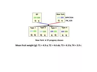
Filter response • Qs of 16, 5 and 40 at 80,95 and 110 MHz
DM-CM response of the filter • CMRR is more than 40dB in the band of interest