SEQUENTIAL LOGIC
SEQUENTIAL LOGIC. A circuit’s output depends on its previous state (condition) in addition to its current inputs The state of the circuit is kept in memory devices The state dependency is accomplished by feedback path. LATCH. Active Low. LATCH. Active High. LATCH APPLICATION.


SEQUENTIAL LOGIC
E N D
Presentation Transcript
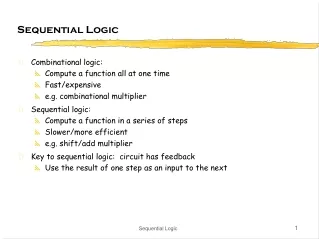
SEQUENTIAL LOGIC • A circuit’s output depends on its previous state (condition) in addition to its current inputs • The state of the circuit is kept in memory devices • The state dependency is accomplished by feedback path C.S. Choy
LATCH • Active Low C.S. Choy
LATCH • Active High C.S. Choy
LATCH APPLICATION • Switch Debounce Almost all mechanical switches have contact bounce problem C.S. Choy
GATED-LATCH Also known as level-triggered • S-C Type • D-Type C.S. Choy
EDGED-TRIGGERED FLIP-FLOP • D-Type C.S. Choy
Positive-Edge Detector • Negative-Edge Detector C.S. Choy
D-TYPE FLIP-FLOP VARIATIONS • Negative-Edge Triggered • With Asynchronous Controls C.S. Choy
TOGGLE FLIP-FLOP The flip-flop changes states on every active clock transition From the waveform, one can observe that when a toggle flip-flop is continuously driven by a clock signal of frequency fin, the output (Q) produces a repetitive waveform of frequency fout=fin/2 Divide-By-2 Circuit C.S. Choy
J-K FLIP-FLOP C.S. Choy
COMMON SEQUENTIAL CIRCUITS • Counters A digital counter is a circuit used to generate binary numbers in a specific count sequence. That sequence is mainly governed by input clock pulses, and it is repetitive as long as these clock pulses are applied. Counters serve two main functions in digital systems – counting and frequency division ASYNCHRONOUS SYNCHRONOUS C.S. Choy
ASYNCHRONOUS COUNTER(RIPPLE COUNTER) Basic building block is a toggle flip-flop Since each flip-flop receives its clock pulse from another flip-flop, there will be delay through these flip-flops. This addition delay is the longest for the MSB flip-flop C.S. Choy
ALTERNATIVE MOD-8 UP-COUNTER C.S. Choy
MOD-16 UP-COUNTER C.S. Choy
COUNTERS OF OTHER MODULUS • Mod-5 C.S. Choy
MISCOUNTS IN ASYNCHRONOUS COUNTER The additive propagation delays produce short duration of miscounts C.S. Choy
MAXIMUM CLOCK FREQUENCY ALLOWED IN ASYNCHRONOUS COUNTERS n – number of stages ff – propagation delay of flip-flop C.S. Choy
SYNCHRONOUS COUNTERS All flip-flops are clocked simultaneously • Mod-16 Synchronous Up-Counter C.S. Choy
MOD-10 SYNCHRONOUS UP-COUNTER (BCD OR DECADE) QA – toggle every time QB – toggle at A high and D low QC – toggle at A and B high QD – change high at A, B and C high but change low afterwards (A high) C.S. Choy
MOD-8 DOWN COUNTER C.S. Choy
MOD-8 SYNCHRONOUS UP/DOWN COUNTER C.S. Choy
PRESETABLE COUNTERS C.S. Choy
SYNCHRONOUS COUNTER DESIGN • Mod-6 Up-Counter Using D-flip-flops • Design table C.S. Choy
MOD-6 UP-COUNTER • K-maps • Final design C.S. Choy
REGISTERS A group of latches or flip-flops used to store, transfer, or shift data • Serial Shift Register Data is clocked into the register bit by bit It is important to note that level-triggered type of latches will not work properly C.S. Choy
AN UNIVERSAL REGISTER C.S. Choy
RING COUNTER The counter is a shift register that has its output connected back to its own input C.S. Choy
JONHSON COUNTER Each bit is toggled in turn • Mod-6 000 100 110 111 011 001 000 With its unique bit pattern, any sequence can be detected with a 2-input gate C.S. Choy
MULTIPLY/DIVIDE REGISTER • A left shift operation multiplies a binary number by a factor of 2 • A right shift operation divides a binary number by a factor of 2 C.S. Choy
PSEUDO-RANDOM-SEQUENCE GENERATOR INVALID CONDITION C.S. Choy