Scaling Internet Routers Using Optics UW, October 16 th , 2003
Scaling Internet Routers Using Optics UW, October 16 th , 2003 Nick McKeown Joint work with research groups of: David Miller, Mark Horowitz, Olav Solgaard. Students: Isaac Keslassy, Shang-Tse Chuang, Kyoungsik Yu. Department of Electrical Engineering, Stanford University

Scaling Internet Routers Using Optics UW, October 16 th , 2003
E N D
Presentation Transcript
Scaling Internet Routers Using OpticsUW, October 16th, 2003 Nick McKeown Joint work with research groups of: David Miller, Mark Horowitz, Olav Solgaard. Students: Isaac Keslassy, Shang-Tse Chuang, Kyoungsik Yu. Department of Electrical Engineering, Stanford University Paper: http://klamath.stanford.edu/~nickm/papers/sigcomm2003.pdf Web site: http://klamath.stanford.edu/or
Backbone router capacity 1Tb/s 100Gb/s 10Gb/s Router capacity per rack 2x every 18 months 1Gb/s
Backbone router capacity 1Tb/s 100Gb/s Traffic 2x every year 10Gb/s Router capacity per rack 2x every 18 months 1Gb/s
Extrapolating 100Tb/s 2015: 16x disparity Traffic 2x every year Router capacity 2x every 18 months 1Tb/s
Consequence • Unless something changes, operators will need: • 16 times as many routers, consuming • 16 times as much space, • 256 times the power, • Costing 100 times as much. • Actually need more than that…
Optical Switch Electronic Linecard #1 Electronic Linecard #625 160-320Gb/s 160-320Gb/s 40Gb/s • Line termination • IP packet processing • Packet buffering • Line termination • IP packet processing • Packet buffering 40Gb/s 160Gb/s 40Gb/s 100Tb/s = 640 * 160Gb/s 40Gb/s Stanford 100Tb/s Internet Router Goal: Study scalability • Challenging, but not impossible • Two orders of magnitude faster than deployed routers • We will build components to show feasibility
Throughput Guarantees • Operators increasingly demand throughput guarantees: • To maximize use of expensive long-haul links • For predictability and planning • Despite lots of effort and theory, no commercial router today has a throughput guarantee.
Requirements of our router • 100Tb/s capacity • 100% throughput for all traffic • Must work with any set of linecards present • Use technology available within 3 years • Conform to RFC 1812
What limits router capacity? Approximate power consumption per rack Power density is the limiting factor today
Crossbar Linecards Switch Linecards Trend: Multi-rack routersReduces power density
Juniper TX8/T640 Alcatel 7670 RSP TX8 Avici TSR Chiaro
Limits to scaling • Overall power is dominated by linecards • Sheer number • Optical WAN components • Per packet processing and buffering. • But power density is dominated by switch fabric
Limit today ~2.5Tb/s • Electronics • Scheduler scales <2x every 18 months • Opto-electronic conversion Switch Linecards Trend: Multi-rack routersReduces power density
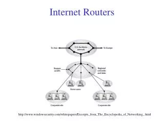
Multi-rack routers Switch fabric Linecard In WAN Out In WAN Out
Question • Instead, can we use an optical fabric at 100Tb/s with 100% throughput? • Conventional answer: No. • Need to reconfigure switch too often • 100% throughput requires complex electronic scheduler.
Outline • How to guarantee 100% throughput? • How to eliminate the scheduler? • How to use an optical switch fabric? • How to make it scalable and practical?
R R ? R R ? Out ? R R ? R R R R ? R R R ? R Out ? R R R R ? ? R Out Switch capacity = N2R Router capacity = NR 100% Throughput In In In
R R/N R/N Out R/N R/N R R R R/N R/N Out R/N R R/N R/N Out If traffic is uniform R In R In R In
R R R R ? R/N In R R/N Out R/N R/N R R R R R In R R R/N R/N Out R/N R R R R/N In R/N Out Real traffic is not uniform
Out Out Out Out Out 100% throughput for weakly mixing, stochastic traffic. [C.-S. Chang, Valiant] Two-stage load-balancing switch R R R R/N R/N In Out R/N R/N R/N R/N R/N R/N R R R In R/N R/N R/N R/N R/N R/N R R R R/N R/N In R/N R/N Load-balancing stage Switching stage
Out Out Out R R In 3 3 3 R/N R/N 1 R/N R/N R/N R/N R/N R/N R R In 2 R/N R/N R/N R/N R/N R/N R/N R R R/N In 3 R/N R/N
Out Out Out R R In R/N R/N 1 R/N R/N 3 R/N R/N R/N R/N R R In 2 R/N R/N 3 R/N R/N R/N R/N R/N R R R/N In 3 R/N R/N 3
Chang’s load-balanced switchGood properties • 100% throughput for broad class of traffic • No scheduler needed a Scalable
FOFF: Load-balancing algorithm • Packet sequence maintained • No pathological patterns • 100% throughput - always • Delay within bound of ideal • (See paper for details) Chang’s load-balanced switchBad properties • Packet mis-sequencing • Pathological traffic patterns a Throughput 1/N-th of capacity • Uses two switch fabricsa Hard to package • Doesn’t work with some linecards missinga Impractical
One linecard R R Out R R Out R R Out Single Mesh Switch 2R/N In 2R/N 2R/N 2R/N In 2R/N 2R/N 2R/N 2R/N In 2R/N
2R/N 2R/N Backplane Out R 2R/N 2R/N 2R/N 2R/N Out R 2R/N 2R/N R/N Out R Packaging R In R In R In
C1, C2, …, CN C1 C2 C3 CN In In In In Out Out Out Out Many fabric options N channels each at rate 2R/N Any permutation network Options Space: Full uniform mesh Time: Round-robin crossbar Wavelength: Static WDM
A, A, A, A A, B, C, D B, B, B, B A, B, C, D C, C, C, C A, B, C, D D, D, D, D A, B, C, D 4 WDM channels, each at rate 2R/N In In In In Out Out Out Out Static WDM switching Array Waveguide Router (AWGR) Passive andAlmost ZeroPower A B C D
2 2 2 2 2 2 l1 R l1, l2,.., lN WDM lN R l1 l1, l2,.., lN R R WDM 2 lN Out l1 R l1, l2,.., lN R 1 1 1 1 WDM lN Linecard dataflow In l1 l1, l2,.., lN R R WDM lN 1 3 1 1 1 1 2 3 4 1 1 1 1
Problems of scale • For N < 64, WDM is a good solution. • We want N = 640. • Need to decompose.
Decomposing the mesh 2R/8 1 1 2 2 3 3 4 4 5 5 6 6 7 7 8 8
WDM TDM Decomposing the mesh 1 2R/8 2R/8 1 2R/4 2R/8 2R/8 2 2 3 3 4 4 5 5 6 6 7 7 8 8
1 L 1 2 2 L When N is too largeDecompose into groups (or racks) Group/Rack 1 2R Array Waveguide Router (AWGR) l1, l2, …, lG 2R 1 2R Group/Rack G 2R l1, l2, …, lG 2R G 2R
When a linecard is missing • Each linecard spreads its data equally over every other linecard. • Problem: If one is missing, or failed, then the spreading no longer works.
R R 2R/3 + 2R/3 = (4/3)R 2R/3 + 2R/6 + 2R/3 + 2R/6 = 2R 2R/3 + 2R/6 Out 2R/3 + 2R/6 R R Out R R 2R/3 + 2R/6 Out 2R/3 + 2R/6 When a linecard fails 2R/3 In 2R/3 2R/3 • Solution: • Move light beams • Replace AWGR with MEMS switch. • Reconfigure when linecard added, removed or fails. • Finer channel granularity • Multiple paths. 2R/3 In 2R/3 2R/3 2R/3 2R/3 In 2R/3
1 MEMS Switch G 1 MEMS Switch G 1 MEMS Switch G L 1 2 1 2 L SolutionUse transparent MEMS switches Group/Rack 1 MEMS switches reconfigured only when linecard added, removed or fails. 2R 2R 2R Group/RackG=40 2R 2R 2R Theorems: 1. Require L+G-1 MEMS switches 2. Polynomial time reconfiguration algorithm
Middle-Stage First-Stage Final-Stage GxG Middle Switch 1 1 Linecard 1 Linecard 1 2 2 LxM Local Switch MxL Local Switch Linecard 2 Linecard 2 3 3 1 Linecard L M M Linecard L GxG Middle Switch Group 1 Group 1 1 1 2 Linecard 1 Linecard 1 2 2 LxM Local Switch MxL Local Switch Linecard 2 Linecard 2 3 3 GxG Middle Switch Linecard L M M Linecard L 3 Group 2 Group 2 1 1 Linecard 1 Linecard 1 2 2 LxM Local Switch MxL Local Switch Linecard 2 Linecard 2 3 3 GxG Middle Switch Linecard L M M Linecard L M Group G Group G Hybrid Architecture: Logical View
Static MEMS Electronic Switches Fixed Lasers Optical Receivers Electronic Switches GxG MEMS 1 1 Linecard 1 Linecard 1 LxM Crossbar MxL Crossbar 2 2 Linecard 2 Linecard 2 3 3 1 Linecard L Linecard L M M GxG MEMS Group 1 Group 1 1 1 Linecard 1 Linecard 1 2 LxM Crossbar MxL Crossbar 2 2 Linecard 2 Linecard 2 3 3 GxG MEMS Linecard L Linecard L M M 3 Group 2 Group 2 1 1 Linecard 1 Linecard 1 LxM Crossbar MxL Crossbar 2 2 Linecard 2 Linecard 2 3 3 GxG MEMS Linecard L Linecard L M M M Group G Group G Hybrid Electro-Optical Architecture
Number of MEMS Switches R R R Linecard 1 Crossbar Crossbar Linecard 1 R R Linecard 2 Linecard 2 R R Linecard 3 Crossbar Crossbar Linecard 3 R R R R R Linecard 4 Linecard 4 StaticMEMS R R R Linecard 1 Crossbar Crossbar Linecard 1 R R R Linecard 2 Linecard 2 R R Linecard 3 Crossbar Crossbar Linecard 3 R R R R Linecard 3 Linecard 4
Number of MEMS Switches R R 4R/3 Linecard 1 Crossbar Crossbar Linecard 1 R R Linecard 2 Linecard 2 R R Linecard 3 Crossbar Crossbar Linecard 3 2R/3 2R/3 R/3 StaticMEMS R R R Linecard 1 Crossbar Crossbar Linecard 1 R/3 R 2R/3 R Linecard 2 Linecard 2 R/3 R R Linecard 3 Crossbar Crossbar Linecard 3 2R/3
Number of MEMS needed for a schedule • Li: number of linecards in group i, 1 ≤ i ≤ G. Group i needs to send to group j: • Assume each group can send at most R to each MEMS. Number of MEMS needed between groups i and j:
Number of MEMS needed for a schedule • The number of MEMS needed for group i to send to group j is Aij. • The total number of MEMS needed for group i is the sum of the Aij’s
Constraints for the TDM Schedule • Latin Square: In any period N, each transmitting linecard is connected to each receiving linecard exactly once. • MEMS constraint: In any time-slot, there are at most Aijconnections between transmitting group i and receiving group j, where:
Example • Assume L1=3, L2=2, L3=1 • Then • E.g., at most 2 packets from the first group to the first group at each time-slot
Configuration Algorithm • Assign connections between groups, so MEMS constraint is satisfied. • Assign group connections to specific linecards, so there is exactly one connection per linecard pair in the schedule. Comments: • Algorithm is surprisingly complex. • Best running time so far: 40 seconds for 640 linecards.
Low-cost, low-power optoelectronic conversion? l1 Pkt Switch How to build a 250ms 160Gb/s buffer? WDM lG l1 R R WDM lG Challenges In l1 Address Lookup l1, l2,.., lG R R WDM lG R l1, l2,.., lG l1, l2,.., lG 1 1 1 2 2 R=160Gb/s 3 4 Out l1 R l1, l2,.., lG R WDM lG
Chip #2: 16 x 55 Opto-electronic crossbar 55 x 10Gb/s 55 x 10Gb/s 1500nm Optical source 16 x 10Gb/s CMOS ASIC To Linecards To Optical Fabric What we are building 250ms DRAM 320Gb/s Chip #1: 160Gb/s Packet Buffer Buffer Manager 90nm ASIC 160Gb/s 160Gb/s Optical Detector Optical Modulator
40 x 40 MEMS Linecard Rack 1 Linecard Rack G = 40 Switch Rack < 100W L = 16 160Gb/s linecards L = 16 160Gb/s linecards 1 2 55 56 100Tb/s Load-Balanced Router L = 16 160Gb/s linecards