Scaling Internet Routers Using Optics
Scaling Internet Routers Using Optics. Isaac Keslassy Department of Electrical Engineering Stanford University http://yuba.stanford.edu/~keslassy/. Outline. Load-Balanced Switch Power Constraints Router Requirements Load-Balanced Switch Architecture Needed Design Properties

Scaling Internet Routers Using Optics
E N D
Presentation Transcript
Scaling Internet Routers Using Optics Isaac Keslassy Department of Electrical Engineering Stanford University http://yuba.stanford.edu/~keslassy/
Outline • Load-Balanced Switch • Power Constraints • Router Requirements • Load-Balanced Switch Architecture • Needed Design Properties • Optical Packaging • Pathological Traffic Patterns • Tolerance to Linecard Failure • Applications
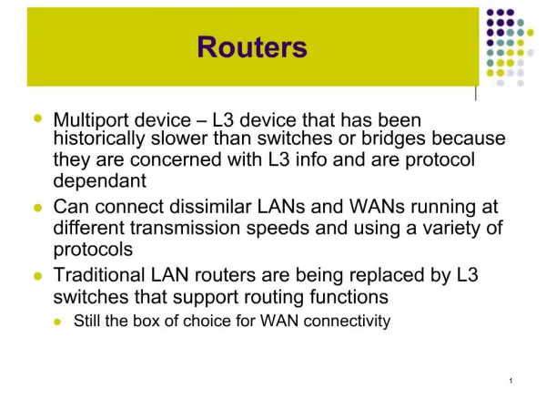
Rack Switch (Crossbar) Linecards Simplified View of Backbone Routers
Backbone router capacity 1Tb/s 100Gb/s 10Gb/s Router capacity per rack 2x every 18 months 1Gb/s
Backbone router capacity 1Tb/s 100Gb/s Traffic 2x every year 10Gb/s Router capacity per rack 2x every 18 months 1Gb/s
What limits router capacity? Approximate power consumption per rack Power density is the limiting factor today
Crossbar Linecards Switch Linecards Trend: Multi-rack routersReduces power density
Juniper TX8/T640 Alcatel 7670 RSP TX8 Avici TSR Chiaro
Limits to scaling • Overall power is dominated by linecards • Sheer number • Optical WAN components • Per packet processing and buffering. • But power density is dominated by switch fabric
Limit today ~2.5Tb/s • Electronics • Scheduler scales <2x every 18 months • Opto-electronic conversion Switch Linecards Trend: Multi-rack routersReduces power density
Opto-Electronic Conversion Switch fabric Linecard In WAN Out In WAN Out
Question • Instead, can we use an optical fabric? • Conventional answer: No. Need to reconfigure switch too often in common architectures
Optical Switch Electronic Linecard #1 Electronic Linecard #625 160-320Gb/s 160-320Gb/s 40Gb/s • Line termination • IP packet processing • Packet buffering • Line termination • IP packet processing • Packet buffering 40Gb/s 160Gb/s 40Gb/s 100Tb/s = 640 * 160Gb/s 40Gb/s 100Tb/s Internet Router? Goal: Study scalability • Challenging, but not impossible • Two orders of magnitude faster than deployed routers
Router Requirement: Throughput Guarantees • Operators increasingly demand throughput guarantees: • To maximize use of expensive long-haul links • For predictability and planning • Despite lots of effort and theory, no commercial router today has a throughput guarantee.
Router Requirements • 100Tb/s capacity • 100% throughput for all traffic • Conform to RFC 1812 • Use technology available within 3 years
Outline • Load-Balanced Switch • Power Constraints • Router Requirements • Load-Balanced Switch Architecture • Needed Design Properties • Optical Packaging • Pathological Traffic Patterns • Tolerance to Linecard Failure • Applications
R R ? R R ? Out ? R R ? R R R R ? R R R ? R Out ? R R R R ? ? R Out Switch capacity = N2R Router capacity = NR 100% Throughput In In In
R R/N R/N Out R/N R/N R R R R/N R/N Out R/N R R/N R/N Out If traffic is uniform R In R In R In
R R R R ? R/N In R R/N Out R/N R/N R R R R R In R R R/N R/N Out R/N R R R R/N In R/N Out Real traffic is not uniform
Out Out Out Out Out Two-stage load-balanced switch R R R R/N R/N In Out R/N R/N R/N R/N R/N R/N R R R In R/N R/N R/N R/N R/N R/N R R R R/N R/N In R/N R/N Load-balancing stage Switching stage 100% throughput for weakly mixing traffic (Valiant, C.-S. Chang)
Out Out Out R R In 3 3 3 R/N R/N 1 R/N R/N R/N R/N R/N R/N R R In 2 R/N R/N R/N R/N R/N R/N R/N R R R/N In 3 R/N R/N
Out Out Out R R In R/N R/N 1 R/N R/N 3 R/N R/N R/N R/N R R In 2 R/N R/N 3 R/N R/N R/N R/N R/N R R R/N In 3 R/N R/N 3
Load-balanced switchGood properties • 100% throughput for broad class of traffic • No scheduler needed a Scalable
Load-balanced switchBad properties • Uses two switch fabricsa Hard to package • Pathological traffic patternsa Packet reorderinga Throughput 1/N-th of capacity • Doesn’t work with some linecards missinga Impractical
Outline • Load-Balanced Switch • Power Constraints • Router Requirements • Load-Balanced Switch Architecture • Needed Design Properties • Optical Packaging • Pathological Traffic Patterns • Tolerance to Linecard Failure • Applications
One linecard R R In R/N R/N Out R/N R/N R/N R/N R/N R/N R R In R/N R/N Out R/N R/N R/N R/N R/N R R R/N In Out R/N R/N From Two Meshes to One Mesh
One linecard R R Out R R Out R R Out Single Mesh Switch 2R/N In 2R/N 2R/N 2R/N In 2R/N 2R/N 2R/N 2R/N In 2R/N
2R/N 2R/N Backplane Out R 2R/N 2R/N 2R/N 2R/N Out R 2R/N 2R/N R/N Out R Packaging R In R In R In
C1, C2, …, CN C1 C2 C3 CN In In In In Out Out Out Out Many fabric options N channels each at rate 2R/N Any permutation network Options Space: Full uniform mesh Time: Round-robin crossbar Wavelength: Static WDM (Wavelength Division Multiplexing)
1 1 1 l l l … , N 1 2 AWGR (Arrayed Waveguide Grating Router) A Passive Optical Component • Wavelength i on input port j goes to output port (i+j-1) mod N • Can shuffle information from different inputs 1 l Linecard 1 Linecard 1 1 Linecard 2 1 l Linecard 2 2 NxN AWGR 1 l Linecard N Linecard N N
Fixed Laser/Modulator Detector l l 1 1 1 N 1 1 l l l l , , l l 1 2 1 2 Linecard 1 Linecard 1 2 2 2 1 l l … … N N l l N N l l 1 1 2 1 l l 2 2 , l l , l l Linecard 2 Linecard 2 1 2 1 2 2 2 2 3 … l l … NxN AWGR N N l l N N l l 1 1 N N-1 N N l l l l , , l l 1 2 1 2 Linecard N Linecard N 2 2 1 N l l … … N N l l N N AWGR Based Solution
A, A, A, A A, B, C, D B, B, B, B A, B, C, D C, C, C, C A, B, C, D D, D, D, D A, B, C, D 4 WDM channels, each at rate 2R/N In In In In Out Out Out Out Static WDM Switching: Packaging Arrayed Waveguide Grating Router (AWGR) Passive andAlmost ZeroPower A B C D
Outline • Load-Balanced Switch • Power Constraints • Router Requirements • Load-Balanced Switch Architecture • Needed Design Properties • Optical Packaging • Pathological Traffic Patterns • Tolerance to Linecard Failure • Applications
Out 2 1 2 1 2 1 Out Out Packet Reordering R R In R/N R/N R/N R/N R/N R/N R/N R/N R R In R/N R/N R/N R/N R/N R/N R/N R R R/N In R/N R/N
Out 1 2 3 1 2 3 1 3 2 Out Out UFS (Uniform Frame Spreading) R R In R/N R/N R/N R/N R/N R/N R/N R/N R R In R/N R/N R/N R/N R/N R/N R/N R R R/N In R/N R/N
FOFF (Full Ordered Frames First) • Algorithm based on UFS • Property 1:FOFF maintains packet order. • Property 2:FOFF maintains an average packet delay within constant from ideal (output-queued, work-conserving) router. • Corollary:FOFF has 100% throughput
Outline • Load-Balanced Switch • Power Constraints • Router Requirements • Load-Balanced Switch Architecture • Needed Design Properties • Optical Packaging • Pathological Traffic Patterns • Tolerance to Linecard Failure • Applications
R R Out R R Out R R Out Linecard Failure 2R/3 In 2R/3 2R/3 2R/3 In 2R/3 2R/3 2R/3 2R/3 In 2R/3
Linecard Rack 1 Linecard Rack G = 40 L = 16 160Gb/s linecards L = 16 160Gb/s linecards 100Tb/s Load-Balanced Router 40 x 40 static MEMS Switch Rack < 100W L = 16 160Gb/s linecards 1 2 55 56 More details: Sigcomm ’03, Infocom ‘04
Outline • Load-Balanced Switch • Power Constraints • Router Requirements • Load-Balanced Switch Architecture • Needed Design Properties • Optical Packaging • Pathological Traffic Patterns • Tolerance to Linecard Failure • Applications
Stanford “Optics in Routers” Project • Objective • Determine the best way to incorporate optics into routers. • Push technology hard to expose new issues. • Photonics, Electronics, System design • Uses the 100Tb/s router architecture • Profs. Mark Horowitz, Nick McKeown, David Miller, Olav Solgaard • http://yuba.stanford.edu/or
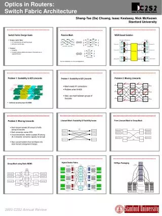
Research Problems • Linecard • Memory bottleneck: Address lookup and packet buffering. • Architecture • Arbitration: Computation complexity. • Switch Fabric • Optics: Fabric scalability and speed, • Electronics: Link electronics, • Packaging: Three surface problem.
? In r r Out ? ? In r r ? In ? r r Out ? ? ? ? Out Backbone Network Model ? • Operator wants to minimize capacity, given the guarantee that it can service any (adversarial) arrival traffic pattern • Network designer allowed any fixed interconnection network and any routing policy (with any number of hops)
Backbone Model • Theorem 1:a specific load-balanced switch achieves the minimum capacity among all possible networks, and is the unique network to do so. • Theorem 2: the load-balanced switch with a uniform mesh is asymptotically optimal as N goes to infinity. • Question: Could the whole Internet backbone be a single optical device?
Conclusion • Switch power density is main bottleneck • Load-balanced switch architecture can overcome this bottleneck and achieve 100% throughput • Proposed practical implementation of load-balanced switch