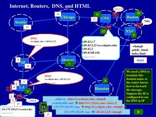
Internet Routers Case Study
Internet Routers Case Study. Eric Keller 4/19/07 and 4/24/07. Outline. Overview/Background Landscape Router components RED/WRED MPLS 5 Example systems (2 Cisco, Juniper, Avici, Foundry) Software Routers. Choices choices…. Interface Speeds. What I’ll focus on

Internet Routers Case Study
E N D
Presentation Transcript
Internet Routers Case Study Eric Keller 4/19/07 and 4/24/07
Outline • Overview/Background • Landscape • Router components • RED/WRED • MPLS • 5 Example systems (2 Cisco, Juniper, Avici, Foundry) • Software Routers
Interface Speeds • What I’ll focus on • Most interesting architectures • Lower end (I think) will all be mostly software • I’ll talk about Click for that Source:Chidamber Kulkarni
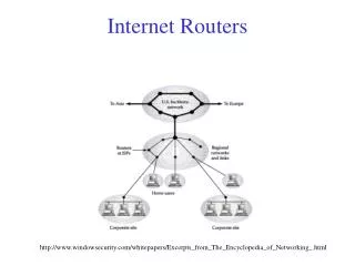
The US backbone Core routers are supposed to be as fast as possible Edge routers are supposed to have the features But, core routers, seemingly, have all the same functionality as edge, just faster (due to blurring) High Performance Switches and Routers, by H. Jonathan Chao and Bin Liu
Internet Routers Components • 4 Basic components common to 4 of 5 systems studied (other had first 3 cards combined) • Interface Cards • Packet Processing cards • Switch Fabric Cards • Control Plane Cards
Ingress Line Card Switch Fabric Egress Line Card Class based queueing of outgoing packets SF Arbiter Egress Scheduler& Shaper TM Scheduler Reassemble Incoming packets Segmentation + header SF Flow Control WRED Discard Data Path Functions Network Processor Ingress Traffic Manager Switch Fabric Egress Traffic Manager - Police - Manage congestion (WRED) - Queue packets in class-based VOQs - Segment packets into switch cells - Queue cells in class based VOQs - Flow control TM per class based VOQ - Schedule class based VOQs to egress ports -Reassemble cells into packets -Shape outgoing traffic -Schedule egress traffic - Parse - Identify flow - Determine Egress Port - Mark QoS Parameters - Append TM or SF Header Source: Vahid Tabatabaee
RED/WRED • Tail Drop – drop packets when queues full or nearly full • TCP global synchronization as all TCP connections "hold back" simultaneously, and then step forward simultaneously • RED – random early detection, uses probabilistic dropping (details on next slide) • Goal: mark packets at fairly evenly spaced intervals to avoid global synchronization and avoid biases, and frequently enough to keep average queue size down • WRED – RED for multiple queues (each with different probabilities)
Multi-Protocol Label Switching (MPLS) • emulates some properties of a circuit-switched network over a packet-switched network. • 32 bit headers used for routing instead of IP address (longest prefix matching) • Popped at each hop • Has quality of service capabilities
Internet Backbone Core Routers • Cisco CRS-1 (2004) • Cisco 12000 (prev generation) • Juniper T-Series (2004) • Avici TSR (2000) • Foundry XMR (2006) • (many failed companies)
Cisco CRS-1 • Cisco’s top end router for the internet backbone • “Modular and distributed routing system” • Scales up to 92 Tbps • Supports OC768c/STM-256c (40Gbps) • Fastest link the backbone carries today • 100 Gbps ready
Models Each slot = 40Gbps Some math: 4*40Gbps = 160 Gbps, But they say 320, why? Fabric shelf – In single shelf config, all switching is contained on cards in this system. In multi shelf config all switching is in its own rack (fabric card shelf)
Recall 4 main components • Interface Cards • Packet Processing cards • Switch Fabric Cards • Control Plane Cards
Cisco CRS-1 example 4 slot shelf • Interface Cards • Packet Processing cards • Switch Fabric Cards • Control Plane Cards Route Processor Switch Fabric Cards on back Multi Service Cards Interface Cards (4 port OC192c/STM-64c)
Route Processor • Performs control plane routing protocols (e.g BGP) • Can control any line card on any shelf (recall-you can connect up to 72 shelves) • 1 redundant in each shelf • One 1.2 GHz PowerPC or Two 800-MHz Power PC symmetric multiprocessing (SMP) • CPUs can only communicate through switch fabric as if they were on a separate card. • Connectivity • Console port (RJ-45 connector) • Auxiliary port (RJ-45 connector) • One 10/100/1000 Ethernet port (RJ-45 connector) • Two 10/100/1000 Ethernet ports for control plane connectivity • Memory/storage • 4 GB of route memory per processor • 64 MB of boot Flash • 2 MB of nonvolatile RAM (NVRAM) • One 1-GB PCMCIA card (internal) • One 40-GB hard drive
Modular Service Card (MSC) • The packet processing engine • 1 for each interface module • Connected via a midplane (built into the chassis) to interface cards and switch fabric cards • Configurable with 2GB of route table memory (but the route processor has 4GB??) • GB of packet buffer memory per side (ingress/egress) • Two SPP – 188 Tensilica CPUs
Silicon Packet Processor (SPP) 16 Clusters of 12 PPEs From Eatherton ANCS05
Switching Fabric • 3-stage, dynamically self-routed Benes topology • Before more details, here’s pic of Benes
Switching Fabric • 3-stage, dynamically self-routed Benes topology switching fabric • Stage 1 (S1)—Distributes traffic to Stage 2 of the fabric plane. Stage 1 elements receive cells from the ingress MSC and distribute the cells to Stage 2 (S2) of the fabric plane. • Cells are distributed to S2 elements in round-robin fashion; one cell goes to the first S2 element, the next cell goes to the next S2 element, and so on • Stage 2 (S2)—Performs switching, provides 2x speedup of cells (two output links for every input link). Stage 2 elements receive cells from Stage 1 and route them toward the appropriate: • egress MSC and PLIM (single-shelf system) • egress line card chassis (multishelf system) • Stage 3 (S3)—Performs switching, provides 2 times (2x) speedup of cells, and performs a second level of the multicast function. Stage 3 elements receive cells from Stage 2 and perform the switching necessary to route each cell to the appropriate egress MSC • Buffering at both S2 and S3 • Uses backpressure - carried in cell header Max 1152 ports?
Switch Fabric (some more info) • 8 Planes + 1 redundant • Cells sent round robin between planes • Supports multicast up to 1 million groups • Separate virtual channels/queues for different priorities • Single shelf system, fabric cards contain all 3 stages • Multi shelf system, fabric cards contain only stage 2, line cards contain stage 1&3
“XYZ selects Cisco CRS-1…” • T-Com (division of Deutsche Telekom) • KT, Korea's leading service provider • SOFTBANK BB - for "Yahoo! BB" Super Backbone • Telstra – Australia • Comcast • China Telecom • Free (Iliad Group) – Fiber to the home in France • Lambda National Rail
Cisco 12000 (GSR) series Internal Name: BFR What about the CRS-1? 6 slot 4 slot Depending on model: 2.5 Gbps/slot 10 Gbps/slot 40 Gbps/slot (so max 1.28 Tbps) 16 slot 10 slot
Switch Fabric • Crossbar switch fabric. • 2.5Gbps fabric has a 16 x 16 crossbar and uses the ESLIP algorithm for scheduling. • 10Gbps fabric has a 64 x 64 crossbar and uses multichannel matching algorithm for scheduling. • Not sure about 40Gbps • 64 Byte Cells are used within the switching fabric. • 8 byte header, 48 byte payload and 8 byte CRC. • It takes roughly 160 nanoseconds to transmit a cell. • Unicast and Multicast data & routing protocol packets are transmitting over the fabric. • Multicast packets are replicated within the fabric and transmitted to the destination line cards by means of partial fufillment. (Busy line cards are sent copies later when they are not busy). • Local traffic on a line card still has to transit the fabric. • e.g. a 40Gbps slot could have 4 10Gbps ports http://cisco.cluepon.net
SCA - Scheduler Control ASIC • During each clock period (160ns) • Sending line cards send a fabric request to the SCA • SCA runs the ESLIP scheduling algorithm • SCA returns a fabric grant to the line card • Line card responds with a fabric grant accept • SCA sets the crossbar for that cell clock • SCA listens for fabric backpressure to stop scheduling for a particular line card http://cisco.cluepon.net
Juniper T-series • TX Matrix • Connects up to 4 T640 • Total 2.56 Tbps • T640 • 16 slots (40 Gbps each) • OC768c • Total 640 Gbps • T320 • 8 slots (40 Gbps each) • Total 320 Gbps
T640 Control Plane Card Interface Cards Packet Processing Cards Switch Fabric Cards
Control Plane Card • 1.6-GHz Pentium IV processor with integrated 256-KB Level 2 cache • 2-GB DRAM • 256-MB Compact flash drive for primary storage • 30-GB IDE hard drive for secondary storage • 10/100 Base-T auto-sensing RJ-45 Ethernet port for out-of-band management • Two RS-232 (DB9 connector) asynchronous serial ports for console and remote management
Packet Processing Card • L2/L3 Packet Processing ASICs remove Layer 2 packet headers, segment incoming packets into 64 Byte data cells for internal processing, reassemble data cells into L3 packets before transmission on the egress network interface, and perform L2 egress packet encapsulation. • A T-Series Internet Processor ASIC performs forwarding table lookups. • Queuing and Memory Interface ASICs manage the buffering of data cells in system memory and the queuing of egress packet notifications. • Priority queue into switch • Switch Interface ASICs manage the forwarding of data cells across the T640 routing node switch fabric. • Switch interface bandwidth “considerably higher” than network interface
Switch Fabric • For single T640 configuration, uses a 16 port crossbar (8 slots, each with 2 PFE’s) • Request, grant • For flow control and fault detection • 4 parallel switch planes + 1 redundant plane • Cell by cell distribution among planes (round robin) • Sequence numbers and reorder buffer at egress to maintain packet order • Fair Bandwidth Allocation (e.g. for when multiple ingress ports write to same egress port) • Graceful degradation (if 1 plane fails, just don’t use it)
Switch Fabric • For multiple T640 configuration, uses a Clos switch (next slide) • The TX Matrix performs the middle stage • The 64x64 switch performed with the same 16x16 crossbars as the T640 • 4 switching planes + 1 redundant plane
Clos networks • 3-stage network (m, n, r) • m = number of middle-staged switches • n = number of input ports on input switches = number o/p ports on o/p switches • r = number of input/output switches • strictly non-blocking for unicast traffic iff • m >= 2n-1 • Rearrangeably non blocking • m >= n What would you expect Juniper’s to be?
Avici TSR • Scales from 40 Gbps to 5 Tbps • Each rack(14 racks max) • 40 router module slots • 4 route controller slots (no details)
Multi Service Connect (MSC)Line Cards • Interface Ports • Up to OC192c • Packet Processing (lookup) • Intel IXP 2400 network processor (next slide) • Meant for 2.5 Gbps processing • ASIC for QoS • Switch Fabric • Router node for the interconnect (in a couple slides) Note: this is 3 of the 4 main components on a single board (which one is missing?)
Interconnect • Bill Dally must have had some input (author of a white paper for Avici) • Topology • 3D Folded Torus 2x4x5 (40 nodes) single rack, 14x8x5 (560) maximal configuration • 10 Gbps links • Routing – source routing, random selection among 24 minimal paths (limited non-minimal supported) • Flow Control – 2 virtual channels for each output port (1120 max), each with their own buffers, one for best-effort, and one for guaranteed rate traffic
Topology Passive backplane 6x4x5 system (3 racks of 2x4x5) On right each circle is 5 line cards (in z direction), backplane connects the 4 quadrants, jumpers connect adjacent backplanes, loop back connectors (jumpers) are placed at edge machines. * So each line represents 5 bidirectional channels (or 10 unidirectional) * In a fully-expanded 14x8x5, 560 line card, system, one set of short cables is used to carry the y-dimension channels between two rows of racks.
Bisection Bandwidth Scaling • Claim: can upgrade 3D torus 1 line card at a time (compare to crossbar, Clos, Benes) • Claims Benes can only double (but Cisco CRS-1 scales to 1152 nodes) speedup 2x2 x-y bisection constant as z dimension is populated from 2x2x2 to 2x2x5 ? 4x5 y-z bisection constant as x dimension populated from 5x4x5 to 8x4x5 8x5 y-z bisection constant as x dimension populated from 8x8x5 to 14x8x5
High Path Diversity • 3D torus has minimal paths • 8x8x8 => 90 6 hop paths (avg message, not longest path) • At least 2 are edge disjoint • Load balance across paths • Routing randomly selects among 24 of the paths • Compare ability to and need to load balance for Crossbar, Clos?
Virtual Networks • 2 virtual channels per output port (best-effort, guaranteed bit rate – 33us) • Max 1120 (14x5x8 torus with 2 per output) • Separate set of flit buffers at each channel for each virtual channels • Acts as an output queued crossbar • Makes torus non-blocking • Shared physical links • Never loaded to more than 2/3 due to load balancing and speedup • 72 Byte flits • worst-case expected waiting time to access a link is 60ns per hop
Foundry NetIron XMR(cleverly named XMR4000, XMR8000, XMR16000, XMR 32000) • 4-, 8-,16-,and 32-slot racks • 40 Gbps per slot • (3 Tbps total capacity) • Up to 10 GigE (can be connected to SONET/SDH networks, but no built in optical) • As of March 2007, they do offer POS interfaces • Highest single rack switching capacity
Packet Processing • Intel or AMCC network processor with offload • NetLogic NL6000 • IPv4/IPv6 multilayer packet/flow classification • Policy-based routing and Policy enforcement (QoS) • Longest Prefix Match (CIDR) • Differentiated Services (DiffServ) • IP Security (IPSec) • Server Load Balancing • Transaction verification
Switch Fabric • Clos with “data striping” (same as planes) • Input queuing • Multiple priority queues for each output • 256k virtual queues • Output “pulls” data • Supports Multicast
Forwarding Tables Just to give some idea on sizes • NetIron XMR “Industry leading scalability” • 10 million BGP routes and up to 500 BGP peers • 1 million IPv4 routes in hardware (FIB) • 240,000 IPv6 routes in hardware (FIB) • 2,000 BGP/MPLS VPNs and up to 1 million VPN routes • 16,000 VLLs/VPLSes and up to 1 million VPLS MAC addresses • 4094 VLANs, and up to 2 million MAC addresses