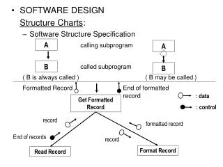
SOFTWARE DESIGN Structure Charts : Software Structure Specification calling subprogram called subprogram ( B is always c
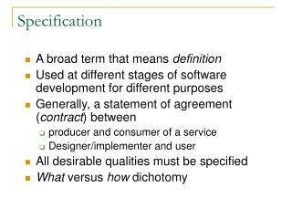
A A SOFTWARE DESIGN Structure Charts : Software Structure Specification calling subprogram called subprogram ( B is always called ) ( B may be called ) Formatted Record End of formatted record B B : data Get Formatted Record : control record formatted record End of records

SOFTWARE DESIGN Structure Charts : Software Structure Specification calling subprogram called subprogram ( B is always c
E N D
Presentation Transcript
A A • SOFTWARE DESIGN Structure Charts: • Software Structure Specification calling subprogram called subprogram ( B is always called ) ( B may be called ) Formatted RecordEnd of formatted record B B : data Get Formatted Record : control record formatted record End of records record Format Record Read Record
B A B Program Structure Charts: A contains one or more calls to module B Predefined Module (debugged and available in library ) Module A conditionally calls Module B depending on decision in A Repetition : Module A calls module B in a loop in module A A B A B
Control starts at root module and is passed down level by level. Control is always returned to the calling module. At the end of program execution, control returns to root module
DFD to Structure Chart : • Transform Analysis Identify the central transform in a DFD • divide processes into those that perform input andediting, processing or transformation and those performing output. • Transaction Analysis Identify the Transaction Center Group of processes between I/Ps and O/Ps With Alternative flows of control depending on condition / user selection • Each DFD process appears as a structure chart module(?) • Additional modules provide details of processing
Transform Analysis (Example) A B C G H P1 P2 P5 P6 D E F P3 P4 Processing Output Stream Input Stream (Central Transform)
The System G C G F C F P5: Make C & F into G Get C Get F Output G F B H B G E H C E Get B P2: Make B into C P6: Make G into H Put H Get E P4: Make E into F E B A D D A P1: Make A into B P3: Make D into E Get D Get A
Transaction Analysis (Example) C E P3 A B P1 P2 P5 G H P6 D F P4 Input Leg Output Leg Processing Center (Transaction Center)
The System G B G B Get B Transaction Center Make B to G Output G A B D G G H H E C A B E F D C F P6 Get A P1 P2 P3 P4 P5 Output H