Download
1 / 56
990 likes | 3.13k Vues
Solid – Liquid Extraction Prepared by Dr.Nagwa El- Mansy Chemical Engineering Department Cairo University. Solid-Liquid Extraction Solid liquid extraction(leaching) means the removal of a constituent from a mixture of solids by bringing the

E N D
Solid – Liquid ExtractionPrepared by Dr.Nagwa El-MansyChemical Engineering DepartmentCairo University
Solid-Liquid Extraction Solid liquid extraction(leaching) means the removal of a constituent from a mixture of solids by bringing the solid material into contact with a liquid solvent that dissolves this particular constituent. Applications:- 1- leaching of soybean oil from flaked soybeans with hexane. 2- Leaching of sugar from sugar beets with hot water.
3- Production of vegetable oils with organic solvents such as hexane , acetone and ether by extraction the oil peanuts , soybeans, sunflower seeds, cotton seeds and halibut livers. 4- Soluble tea is produced by water leaching of tea Leaves. 5- Gold is leached from its ore using an aqueous sodium cyanide solution. 6- Extraction of copper oxide from low grade ores with dilute H2SO4 acid.
Mechanism of leaching:- Extraction involves two steps which are:- 1- Contacting step:- of solvent and the material to be Treated, so as to transfer soluble constituent to the Solvent. 2- Separation step:- of the solution formed from the relatively exhausted solids. The above two steps may be conducted in separate Equipment or in one and the same equipment. Solution resulting from separation step is termed Overflow, Solids left over are termed Underflow.
Extraction Terminology:- 1-Contacting Step:- Basically it’s a mass transfer step , it aims at transferring The soluble constituent from the solid phase into the liquid phase by diffusion and dissolution. The solute is first dissolved from the surface of the solid, then passes into the main body of the solution by diffusion. This process may result in the formation of pores in the solid material which exposes fresh(new) surfaces to subsequent solvent penetration to such surfaces.
An ideal contacting (mixing) stage yields a product in Thermodynamic Equilibrium→ No mass transfer. No heat transfer. No momentum transfer. Why its difficult to reach an ideal stage behavior, thermodynamic equilibrium ? * The rate of mass transfer is slow due to the pore resistance:- the rate of diffusion of solute out of the pores(capillaries) into the bulk solution are very slow. * Some part of the contained solute is not exposed to the solvent(inside a non-porous layer or closed pores).
* Sometimes the adsorption of the solute on the surface of the solid is > than the solubility in the solvent, so the realization of an ideal stage needs rather long times if the operations is carried out batch wise or an Excessively large apparatus if the operation is continuous. How to increase the rate of mass transfer? 1- Increase the agitation speed, thickness of the boundary Layer decreases. 2- As the temperature increase, the solubility increase, Hence, the diffusion increases , the viscosity decreases leading to decrease in the film thickness , hence the pore resistance decreases.
3-Size reduction of solid to increase the exposed mass transfer area. 2-Separation step:- This is a momentum transfer step that can be carried out by (settling or filtration). Calculations:- The design problem of calculating number of theoretical stages require simultaneous solution of material balance and equilibrium relations. We have three component system:- 1- solute (A) 2- Inert solid(B) 3- Solvent (S)
Representing the three component system on right angle triangle:-
Equilibrium Relations:- A-Locus of under flow:- 1- The mass of solution retained/unit mass of inert insoluble solids is obtained experimentally as a function of solution composition YA. The data is usually available in tabular form.
2- In some cases the solution retained/kg solids is approximated constant. i.e independent of composition. This means that the locus of underflow is a line parallel to the hypotenuse.
3-Locus is a straight line:- Locus between two points ( 0, 0.8 ) & ( 0.4, 0 )
B- Locus of overflow:- Also the overflow consists generally of solution only ,i.e (solid-free or inert-free) its locus is:- 1- The hypotenuse. 2- In some cases the overflow contains 10% solids and 90% solution. B : A + S 10 : 90 xB = B / ( A + B + S ) = 0.1
3- ………..and the overflow from the first stage contains 10% from the solids in the feed.
Ideal Extraction Stage:- Ideal extraction stage indicates whether or not we are close to thermodynamic equilibrium. The ideal stage in leaching is represented as a straight line going through point (B) and cutting the two locus in x1 and y1.
Methods of Operation (Types of contact):- 1-Simple single stage:- Considering a theoretical extraction stage where L0 with composition x0 is brought into contact with a solvent V0 having composition y0 . The amount L1 and Composition x1 of the product underflow as well as the amount V1 and comp. y1 of the overflow are to be determined. determ
3- Multi-stage counter current contact:- Considering a feed with rate L0 and composition x0 which is to be treated with a solvent having a composition yn+1 at a rate of Vn+1. The weight fraction in the U.F shouldn’t exceed a given value xnA.
To determine the number of ideal stages required to achieve this extraction duty use the following steps:- The overall M.B on the n stages may be written as:- * x0 , yn+1 , and xn are located from the specifications of the problem. * xM, x0 and yn+1 lies on the same straight line where xM Divides the distance between x0 and yn+1 in the ratio of Vn+1 / L0.
M being the sum of Ln and V1, the points xn,xM,y1 lies on one straight line. Hence y1 may be located by Extrapolating xnxM to meet the locus of the overflow.
Condition of infinite number of stages:- To increase overflow composition the number of stages must be increased. the number of stages increases till reaching the maximum overflow composition (y1max). Steps:- Connect yn+1 with (B) To cut U.F locus in x n min connect it with xM then extend the line to cut O.F in y 1max.
Stage Efficiency:- A deviation between the behavior of actual and Theoretical stages is expected. In theoretical stage:- (Solvent/ Solute) O.F = (Solvent/ Solute) U.F Actual stage is less efficient because:- 1- Slow rates of mass transfer resulting in unattainment of T.D.E (complete dissolution) in the contact time provided for the stage. 2-The solute is adsorbed by the solid to a higher content than the solvent.
3- The pore structure of the solid-solute mixture is such that only a portion of the solute is accessible to the solvent. Calculation of actual number of stages:- A- Construction when overflow efficiency is known:- The tie line representing an actual stage passes no Longer through the origin (B).
B- Construction when underflow efficiency is known:- The tie line representing an actual stage passes no Longer through the origin (B).
Solids-free coordinates:- The construction is in general less crowded than in the case of triangular diagram. No calculations are needed before plotting the equilibrium relations ,but the same procedures described before are followed. The amounts of various streams should be expressed on solid-free basis. Some notes on Rectangular Diagram System:- The abscissa X (weight fraction of solute on a solid-free basis in the U.F) and Y (weight fraction of solute on a solid-free basis in the O.F) is plotted against the amount N (concentration of insoluble solids on the solid-free basis).
A typical equilibrium diagram is shown in the following Figure. The lower curve of N vs yA , where N = 0 on the axis, represents the locus of overflow(where all the solids has been removed). The upper curve N vs xA , Represents the locus of underflow. The tie lines are vertical, and on x-y diagram, the Equilibrium line is yA = xA
Types of contact:- • Simple Single Stage:-The application of material balance equations in conjunction with such diagram , the quantities of various streams should be expressed on solid-free basis. L0 = mass of feed. = (A+B) or (A+B+S). L0’= mass of feed on solid Free-basis = (A) or (A+S). V0= mass of solvent = (S+A) V0’= mass of solvent on solid Free-basis = (S+A).
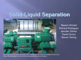
Equipments in leaching:- 1- Fixed-bed leaching:-