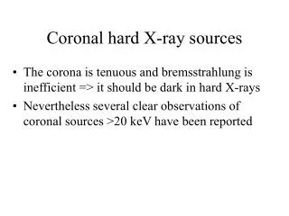
Download
1 / 30
300 likes | 403 Vues
Discussing the implementation and considerations of multi-turn ERL designs for X-ray sources, including advantages and challenges related to space charge forces, HOM heating, RF power requirements, and collective instabilities. The paper delves into the layout at Cornell and implications for various accelerator projects worldwide.

E N D
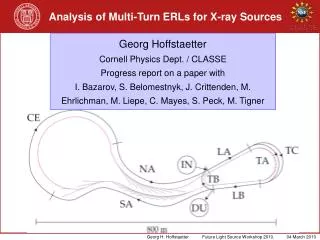
Analysis of Multi-Turn ERLs for X-ray Sources Georg HoffstaetterCornell Physics Dept. / CLASSEProgress report on a paper withI. Bazarov, S. Belomestnyk, J. Crittenden, M. Ehrlichman, M. Liepe, C. Mayes, S. Peck, M. Tigner
ERL Layout at Cornell Cornell Electron Storage Ring Tunnel 2: deceleration to 2.2GeV 3: turn around with 2.2GeV 8: dump at 10MeV 1: injector 2: acceleration to 2.8GeV 3: turn around with 2.8GeV 4: acceleration to 5GeV 5: to x-ray beamlines 6: return through CESR 7: further x-ray beamlines
Advantages • Less linac length and less tunnel length • Less capital investment • Less static heat load • Less dynamic heat load • These seem so tempting and obvious that • eRHIC has been contemplating a 5-turn ERL • MEeIC has been contemplating a 3-turn ERL • LeHC has been contemplating a multi turn ERL • KEK compact ELR plans for 2 turns, 5GeV ERL plans for 2 turn • NPGS is plans a 2 turn ERL • bERLinPro would like to include a 2 turn ERL • JLAB-ligh source goes to 2 turn (initially without ERL, possibly later with ERL) • The pandemic is spreading, but is it analyzed sufficiently to bear promise?
Concerns • Space charge forces for superimposed beams and emittance growth. • Intra beam scattering between superimposed beams and halo/background creation. • Increasing Higher Order Mode (HOM) power for separated bunches. • More sophisticated Beam spectrum and RF control. • Tighter orbit and return time tolerances. • Limits of orbit corrections for 4 simultaneous beams. • Linac optics for 4 simultaneous beams. • Reduced Beam-Breakup (BBU) tolerances. • Reduced effectiveness of polarized cavities and coupled optics for fighting the BBU instability. • Impedance budget and increased energy spread.
Space charge forces for superimposed beams in one bucket The high energy beam with adiabatically damped emittance is inside the wider low energy beam and produces strong space charge forces. Analytic estimate: 1.9micron/meter for a 0.3micron initial emittance
Space charge forces for superimposed beams in one bucket Bunches have to be separated in RF phase ! The high energy beam with adiabatically damped emittance is inside the wider low energy beam and produces strong space charge forces. Analytic estimate: 1.9micron/meter for a 0.3micron initial emittance
HOM heating due to more bunch charge With twice the bunch charge there is the potential for 4 times the HOM heating. But if bunches are well separated, one expect only 2 times the HOM heating. The wake diminishes quickly after the bunch, giving the potential for close to only 2 times the HOM heating for slightly separated bunches.
ERL Layout at Cornell 4 degree bunch separation is sufficient to have only 2.5 times the HOM power.
More complex bunch spectrum Even for separated bunches, the basic frequency remains 2.6GHz and the bunch spectrum thus has the same lines, only with different weights, up to 2 times as large. Should be no problem !
RF power requirenments RF needs are given by return time errors and microphonic detuning. Detuning: 0Hz 10Hz 20Hz In a two turn ERL there are three return loops instead of one. Simple estimate: Three times the RF need for the same return time tolerances. Additional RF installation is expensive !
BBU: Collective Instabilities Higher Order Modes
Single cavity BBU BMAD-BBU: Uses the BMAD lattice and readily computes BBU Single cavity BBU compares superbly with estimates from the 2005 Hoffstaetter – Bazarov PRST-AB BBU paper.
Single cavity 2 turn BBU Rough estimate for multi turn form 2005 paper: approximately factor of n*(n+1), i.e. 6 less current in a 2 turn ELR.
X-ray ERL BBU 1 vs 2 turn Full optics calculation: With TTF like HOM characteristics and No frequency spread 10mHz frequency spread One turn: 12mA Two turn: 6mA One turn: 235mA Two turn: 53mA With optimized 7-cell cavities One turn: 30mA Two turn 8mA One turn: 307mA Two turn: 87mA 30mA seems low, but (2006 Paper by Song & Hoffstaetter) HOM frequency spread leads to a factor of 16 improvement HOM polarization by 50MHz and a coupled optics leads to an additional factor of 5 improvement. (2007 Paper by Hoffstaetter, Bazarov, Song) For Cornell’s 1turn x-ray ERL: potential for 2A BBU limit However, polarization couples x to y in a 1 turn ERL, but back to x in a 2 turn ERL, an thus does not work as well. Estimate: a 100mA threshhold may bearly be met with frequency spread in a 2 turn ERL.
Optimize shape of cavity (>70 parameter…) to minimize cryogenic losses and maximize limits to beam current Understand sensitivity of optimized design to fabrication errors; find “sloppy” parameter! Main Linac Cavity Optimization Higher-Order-modes Red: Optimized cavity; blue: perturbed cavities
Cavities with misalignments R/Q and Q in cavities with misalignments can be significantly worse then expected, but orders of magnitude. (Here for 1/16mm construction error) A very good safety margin for BBU is therefore needed.
Reason for high sensitivity of HOMs Trapped TTF HOMs: Construction errors in cells change the individual cell’s HOM frequencies and hinder good coupling between cells, leading to trapped modes with much larger Q.
Perturbatio: Baseline Center Cell (minimize cryo-load) and optimized end cells (HOM damping) +-1/16 mm perturbations, 400 cavities
Center Cell (optimized HOM passband widths), optimized end cells (HOM damping) +-1/16 mm perturbations, 400 cavities
Center Cell (optimized HOM passband widths), optimized end cells (HOM damping) +-1/8 mm perturbations, 400 cavities
Improved center cell with increased width passbands Preliminary optimized end-cells, no perturbations, 10 MHz HOM frequency spread One turn BBU Threshold current 1000 simulations
Improved center cell with increased width passbands, and deformations +- 1/16 mm perturbations, no additional HOM frequency spread One turn BBU Threshold current
Detuning from deformations +- 1/16 mm perturbations, no additional HOM frequency spread 1 MHz only!
Will lower frequency help? Lower frequencies can help for BBU, but is expensive because of larger heat load and construction cost.
2-turn ERL operation Cornell Electron Storage Ring Tunnel 1: injector 2: acceleration to 2.5GeV 3: return to the East 4: 2.5GeV turnaround to the linac 5: acceleration to 5GeV 6: to x-ray beamlines 7: return through CESR 8: 5GeV beam separation 9: 5GeV turnaround to the linac 10: deceleration to 2.5GeV 11: return to East 12: 2.5GeV turnaround to linac 13: deceleration to 2.5GeV 14: dump at 10MeV
Conclusion • Space charge forces for superimposed beams and emittance growth. • Intra beam scattering between superimposed beams and halo/background creation. • Increasing Higher Order Mode (HOM) power for separated bunches. • More sophisticated Beam spectrum and RF control. • Tighter orbit and return time tolerances. • Limits of orbit corrections for 4 simultaneous beams. • Linac optics for 4 simultaneous beams. • Reduced Beam-Breakup (BBU) tolerances, esp. with cavity errors. • Reduced effectiveness of polarized cavities and coupled optics for fighting the BBU instability. • Impedance budget and increased energy spread.